
Automatic Gain Control ( AGC )
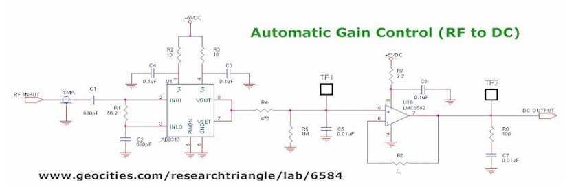
The digital Automatic Gain Control (AGC) system described utilizes the PIC16F876 microcontroller (MCU) to dynamically adjust the gain of an audio or RF signal. The system is particularly designed to prevent over-driving the analog-to-digital converter (A/D) that follows the signal processing stages, ensuring that signals remain within a specified range. The core component of this AGC system is the AD8313, a logarithmic detector/controller that translates an RF input signal into a decibel-scaled DC output.
The RF signal is first coupled through a 20dB TCD-20-4 coupler, which allows the AD8313 to sample the signal without significantly affecting its amplitude. The output from the AD8313 is interfaced with the PIC16F876 via an operational amplifier configured as a voltage follower. This configuration ensures that the output impedance is low, allowing for accurate voltage readings by the microcontroller's A/D converter.
The reference voltage for the A/D converter is set at 4.096V, resulting in a resolution of 4mV per step due to the 10-bit resolution of the A/D. The microcontroller continuously monitors the A/D readings. If the reading exceeds a predetermined threshold, the system activates a digital attenuator, specifically the HMC273MS10G, which provides a maximum attenuation of 31dB in 1dB increments. This allows for precise control over the signal gain. Conversely, if the signal level drops below the acceptable range, the attenuator is deactivated to allow for maximum signal gain.
To provide visual feedback regarding the signal levels, two LEDs are incorporated into the circuit. The red LED indicates when the input signal is too low, while the green LED lights up when the signal is too high. Both LEDs remain off when the signal is within the desired range.
The SGA-6389 SiGe HBT MMIC amplifier is employed in this design, providing approximately 14dB of gain with an output third-order intercept point (IP3) of +35dBm, which is suitable for the intended applications in PCS, iDEN, or CDMA frequency bands. The PIC16F876 MCU, with its 8K of FLASH memory and multiple I/O and A/D channels, offers flexibility for future enhancements. Potential expansions include the integration of a temperature sensor to monitor the amplifier's thermal state, which could trigger a fan if the temperature exceeds safe operating limits, or utilizing the AD8313 as a power meter for additional functionality.
This AGC system serves as a foundational element for further projects, demonstrating the potential for scalable and versatile signal processing solutions in various RF applications. This project is a digital Automatic Gain Control (AGC”) system using a PIC16F876 MCU. The ability to set the gain level in a circuit and have it control itself is a very useful function. This circuit is a building block of another project I am working on. A 30W power amp for either the PCS, iDEN or CDMA frequency bands. I will settle on one of those frequencies sometime soon. I needed to control the gain so the signals for a digital downconverter (DDC) and digital upconverter (DUC) would be in a specific range so the A/D that processes the IF of the mixers does not get over-driven by the amplitude of the input signals. Using a digital attenuator, logarithmic detector / controller, and a MCU with an A/D converter I was able to accomplish this task fairly easy with minimal components.
The heart of this AGC system is the AD8313 logarithmic detector / controller. It is a demodulating logarithmic amplifier that converts an RF signal to an equivalent decibel-scaled value of DC at its output. The RF input is sampled by the AD8313 through a 20dB (TCD-20-4) coupler. The AD8313 is connected to the PIC16F876 A/D via an op-amp configured as a voltage follower. I used a 4.096VDC as the reference voltage giving me a step size of 4mV since the A/D is 10-bits. If the A/D reading is too high it starts turning on attenuators to decrease gain. If the signal is too high, the attenuators are turned off. I placed a red LED and a green LED in the circuit for when the signal is too low or too high (face it, everybody likes to see LEDs light up!).
When the input signal is too low, the red LED is on. While the signal is too high, the green LED comes on. If the signal is within tolerance, both LEDs are off. The HMC273MS10G digital attenuator has a max attenuation of 31dB with increments in steps of 1dB. The amplifier used was a SGA-6389 SiGe HBT MMIC amplifier. The gain on this amplifier was roughly 14dB and provided a IP3 of +35dBm. The PIC16F876 has 8K of FLASH as well a bunch of I/O and A/D channels left for other operations. I may even use the USART of the PIC to be able to control the gain of the system via RS232. Could attatch a temp sensor to control the temperature of the overall assembly. If the amplifier gets too hot, turn a fan on. Or even use the AD8313 as a power meter of sorts. There are so many ideas I don’t want to list them all!!! Special note: Many THANKS goes out to Dale Botkin and Edson Brusque for suggestions with the CCS compiler!! This code as well as the little bit of schematic provided can be used as you wish. If you find it useful don't hesitate to drop me a line, I would love to hear about the uses of the AD8313 or PIC in AGC systems that other people have done.
🔗 External reference
Related Circuits

A voltage-controlled oscillator using the NE555. This circuit is commonly referred to as a voltage-to-frequency converter because the output frequency is altered by varying the input voltage. As previously noted, pin 5 serves as the voltage control terminal, which...
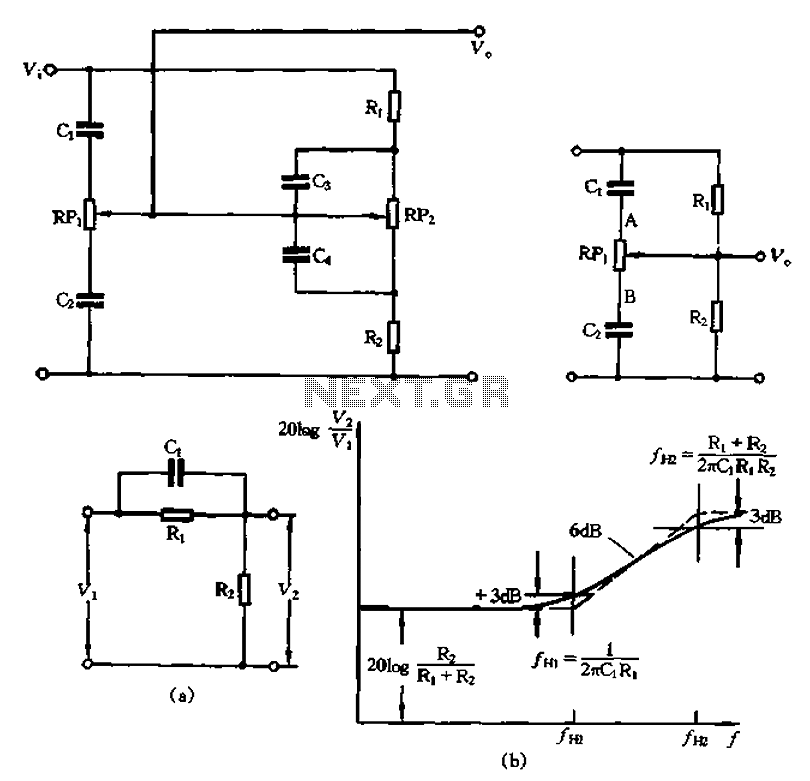
The circuit illustrated in Figure 1-560 represents a treble control potentiometer. Due to the larger capacitance values of C3 and C4 compared to C1 and C2, high-frequency signals can treat C4 as a short circuit. Consequently, the treble adjustment...
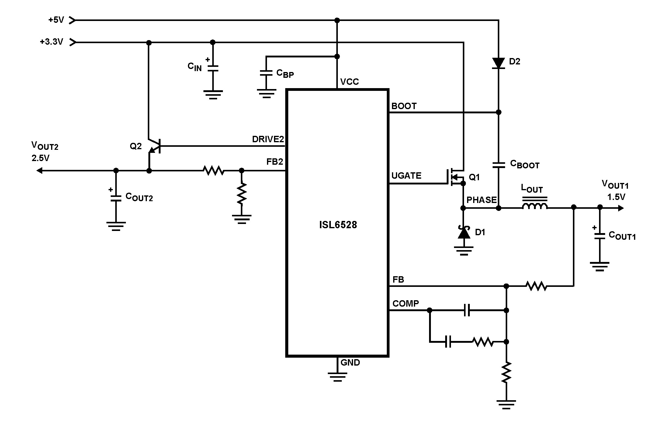
The ISL6528 offers power control and protection for two output voltages in high-performance graphics cards and other embedded processor applications. This dual-output controller drives an N-Channel MOSFET in a standard buck topology and an NPN pass transistor in a...

Manufacturer of thermoelectric materials, custom thermoelectric coolers, and value-added thermal assemblies. The manufacturer specializes in the development and production of thermoelectric materials, which are essential for converting temperature differences into electric voltage and vice versa. These materials are utilized in...
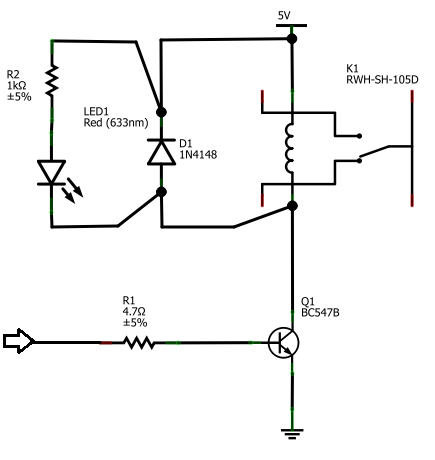
The BC547B transistor has a collector-base voltage (Vcbo) of 50V, a collector-emitter voltage (Vceo) of 45V, and an emitter-base voltage (Vebo) of 6V. In contrast, the BC548 transistor in the original circuit has a Vcbo of 30V, a Vceo...
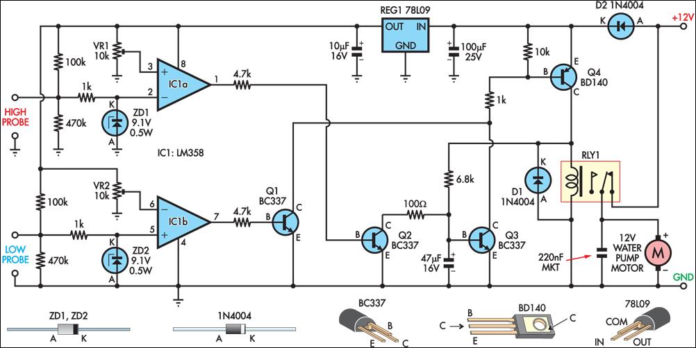
This circuit operates an automotive windscreen washer pump to fill a 20-litre drum from a 205-litre water reservoir. The drum is suspended above a drip line, which irrigates a vegetable garden. Two stainless steel probes mounted in the drum...
Warning: include(partials/cookie-banner.php): Failed to open stream: Permission denied in /var/www/html/nextgr/view-circuit.php on line 713
Warning: include(): Failed opening 'partials/cookie-banner.php' for inclusion (include_path='.:/usr/share/php') in /var/www/html/nextgr/view-circuit.php on line 713