
reservoir pump controller
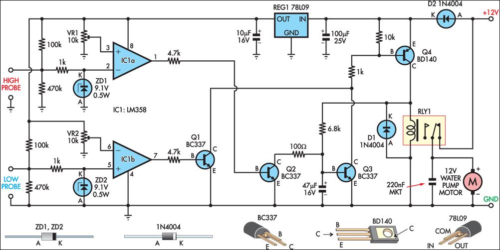
The circuit employs a robust design to manage the water filling process effectively. The use of stainless steel probes allows for reliable sensing of water levels, ensuring accurate operation. The operational amplifiers act as voltage comparators, providing a stable reference for the water level detection. The relay (RLY1) is crucial for controlling the pump, providing isolation and handling higher currents required by the pump motor.
The system's reliance on a 12V automotive relay ensures compatibility with standard automotive components, making it suitable for outdoor applications. The use of trimpots (VR1 and VR2) allows for fine-tuning of the voltage thresholds, accommodating variations in water conductivity or component tolerances. The inclusion of zener diodes and series resistors enhances the durability of the circuit by safeguarding sensitive components from voltage spikes or electrostatic discharge.
The latching mechanism implemented with Q1, Q3, and Q4 ensures that once the pump is activated, it remains operational until the high water level is reached, providing efficient filling without unnecessary cycling. The capacitor's role in preventing premature activation of the latching circuit upon power-up is critical for system stability.
The power supply configuration, utilizing an old car battery charged by a solar panel, highlights the circuit's suitability for remote or off-grid applications, ensuring sustainability and independence from conventional power sources. Overall, this circuit exemplifies effective engineering principles in creating an automated irrigation solution.This circuit operates an automotive windscreen washer pump to fill a 20-litre drum from a 205-litre water reservoir. The drum is suspended above a drip line, which irrigates a vegetable garden. Two stainless steel probes mounted in the drum act as sensors for the system. One probe is positioned at the high water mark, the other at about half-full. The pump power is switched by a 12V automotive relay (RLY1). Two op amps (IC1a & IC1b) connected as voltage comparators form the basis of the circuit. Initially, assume a falling water level with the pump switched off. When the water level exposes the lower probe, the non-inverting input (pin 5) of IC1b rises to about 7. 4V. With trimpot VR2 correctly adjusted, this will be higher than the voltage on pin 6. The output (pin 7) therefore swings high, biasing Q1 into conduction. This in turn causes Q4 to conduct, switching on the relay and starting the pump. In addition, when Q4 switches on it supplies base current to Q3 via a 6. 8kO resistor. Initially, this current flows through the 47 µF capacitor, but once its base-emitter voltage reaches about 0.
6V, Q3 conducts. This action latches Q4 in the "on" state, as its base current can flow to ground via Q3 when Q1 stops conducting which will occur when the rising water level reaches the low probe. When the water level reaches the high probe, the voltage on the non-inverting input (pin 2) of IC1a decreases markedly due to the conductivity of the water.
If trimpot VR1 is correctly adjusted, the output (pin 1) swings high, switching on Q2. This discharges the 47 µF capacitor and robs Q3 of its base current, switching this transistor off. This in turn switches off Q4 and the relay. The zener diodes and 1kO series resistors at the probe inputs protect the op amp`s high impedance inputs from the effects of static discharge. The 47 µF capacitor in parallel with the base-emitter junction of Q1 prevents the latching function from being activated when power is applied to the circuit.
The author`s setup is powered from an old car battery charged from a 12V solar panel. 🔗 External reference
Related Circuits
The clip sync output to TTL level appears to require additional time to accommodate extra components on the board. As a temporary solution, a ZPD4.7 (4.7 V Zener Diode) should be placed between SG and ground at the power...
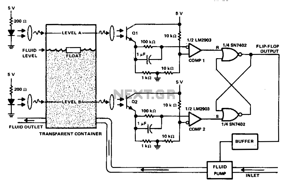
This circuit can be used to maintain fluid between two levels. Variations on this control circuit can be made to keep something that moves within certain boundary conditions. The described circuit functions primarily as a fluid level control system, designed...
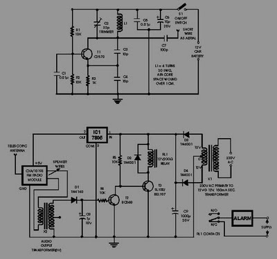
This circuit of an FM radio-controlled anti-theft alarm can be utilized with any vehicle that has a 6 to 12-volt DC supply system. The mini VHF FM transmitter is installed in the vehicle during the night when it is...

Frequency-to-voltage converters are integral components in various instrumentation circuits and are also utilized in radio applications as FM demodulators. A notable configuration for these applications is the Diode Charge Pump circuit (DCP), which additionally serves as an AM detector....
This project addresses the need for a simple circuit that can dim LED lights or control the speed of 12V DC motors. The circuit utilizes Pulse Width Modulation (PWM) to manage the effective or average current flowing through an...
Have you verified whether you can see the zero crossings on your input pin? It may be beneficial to write a sketch that toggles the LED on pin 13 every 50 or 60 zero crossings. This should result in...
Warning: include(partials/cookie-banner.php): Failed to open stream: Permission denied in /var/www/html/nextgr/view-circuit.php on line 713
Warning: include(): Failed opening 'partials/cookie-banner.php' for inclusion (include_path='.:/usr/share/php') in /var/www/html/nextgr/view-circuit.php on line 713