
microcontroller 12V relay circuit converted to 5V relay under uC control

The BC547B and BC548 transistors are both NPN bipolar junction transistors commonly used for switching and amplification applications in electronic circuits. The BC547B is rated for higher voltage levels, making it suitable for applications where higher collector-emitter voltages are present. When designing circuits that involve inductive loads, such as a water pump, it is essential to consider the implications of electromagnetic interference (EMI) and back EMF generated by the inductive load. This feedback can cause voltage spikes that may exceed the breakdown voltages of the transistors and relays, leading to component failure. To mitigate this risk, the use of snubber circuits or flyback diodes is recommended to safely dissipate the energy generated by the inductive load.
For the 1HP water pump, which operates at 220VAC and draws 800W, selecting an appropriate relay is crucial. A relay rated for at least 30A is advisable to ensure it can handle the inrush current when the pump starts. The relay should also have a suitable coil voltage to match the control circuit. Additionally, using a relay with built-in protection against arcing, such as those with zero-crossing detection, can further enhance reliability.
Regarding the assembly on a veroboard, while this may work for low-power applications, for higher loads like the water pump, it is prudent to consider more robust materials. Using a printed circuit board (PCB) designed for higher current applications can provide better durability and reliability. The minimum wire gauge for the pump should be determined based on the current rating; typically, a wire gauge of 14 AWG or thicker would be recommended for 30A applications to minimize voltage drop and heat generation.
For connectors, terminal blocks are an excellent choice as they provide secure connections and facilitate easy disconnection when maintenance is required. It is advisable to select terminal blocks rated for the same or higher current than the relay to ensure safety and reliability in the circuit. Proper insulation and strain relief should also be considered in the design to prevent accidental short circuits or disconnections during operation.The BC547B has Vcbo=50V, Vceo=45V, Vebo=6V, where-as the BC548 in original circuit has Vcbo=30V, Vceo=30V, Vebo=5V, rest of the parameters being pretty same as per datasheet (hFE:220-450). 1HP Water pump (220VAC, 800W) - One thought is to use higher current rated (e. g. 30A) relay. But, I think I need to worry about EM feedback which might cause arcing and destroy the EM relay. Q3) Right now I am making this on a veroboard (el-cheapo phenolic kinds). While I understand that this may be sufficient for the lamp/fan control, I am wondering if I need something better for higher loads, s. a. the Water-pump control What is the minimum gauge wire to be used for this purpose What kind of connectors (terminal blocks) could be used
🔗 External reference
Related Circuits
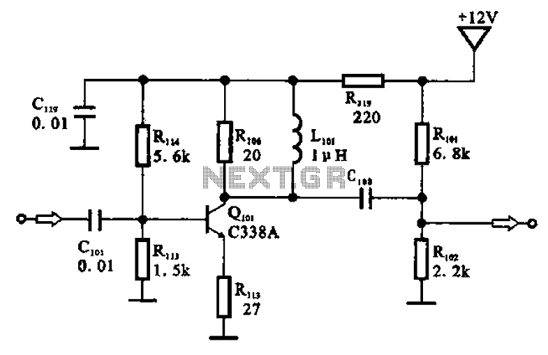
The amplifier circuit is designed as a pre-amplifier configuration. It utilizes transistor Q101 and other components such as inductor L101 and biasing elements. The transistor operates as a common emitter intermediate frequency (IF) amplifier. The IF signal is coupled...
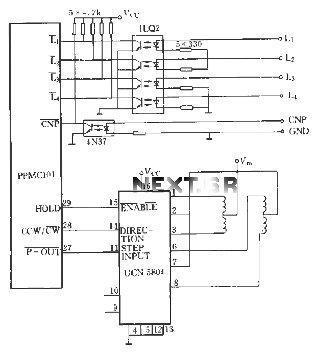
The PPMC external UChl 5804 demonstrates a four-phase stepping motor drive integrated circuit (IC) that is depicted in a downward motion. It utilizes the P-OUT, counterclockwise (ccw) / clockwise (cw), and HOLD outputs. The UCN5804 pins 9 and 10...
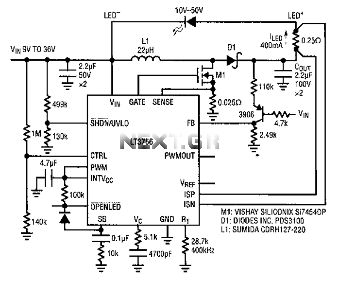
Common LED driver requirements include a wide and overlapping range of LED string voltages and input voltages. Many designers prefer to use an LED driver circuit that accommodates various battery power sources and multiple LED strings. This universal configuration...
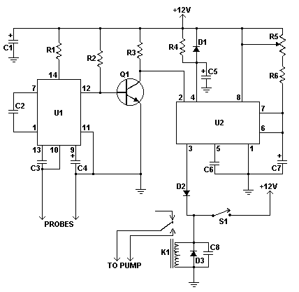
This moisture detector with pump controller is built around the special purpose LM1830 IC. The LM1830 is designed to detect moisture by passing an AC current through a set of probes. An internal comparator compares the resistance of the...
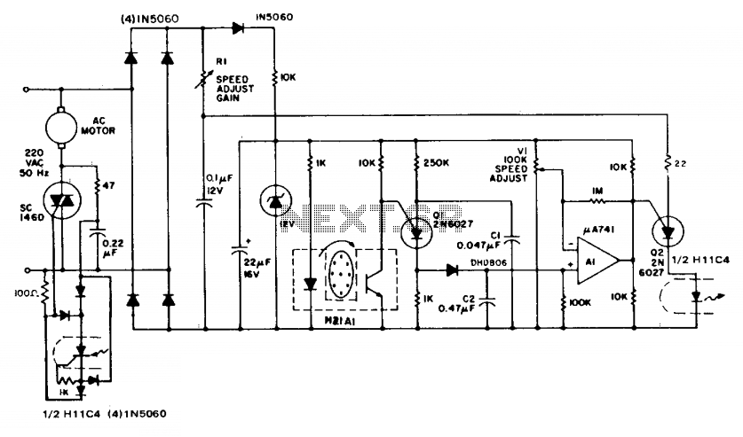
The circuit demonstrates feedback speed regulation for a standard AC induction motor, a task that is typically challenging to achieve without the use of an expensive generator-type precision tachometer. When the apertured disc connected to the motor shaft allows...
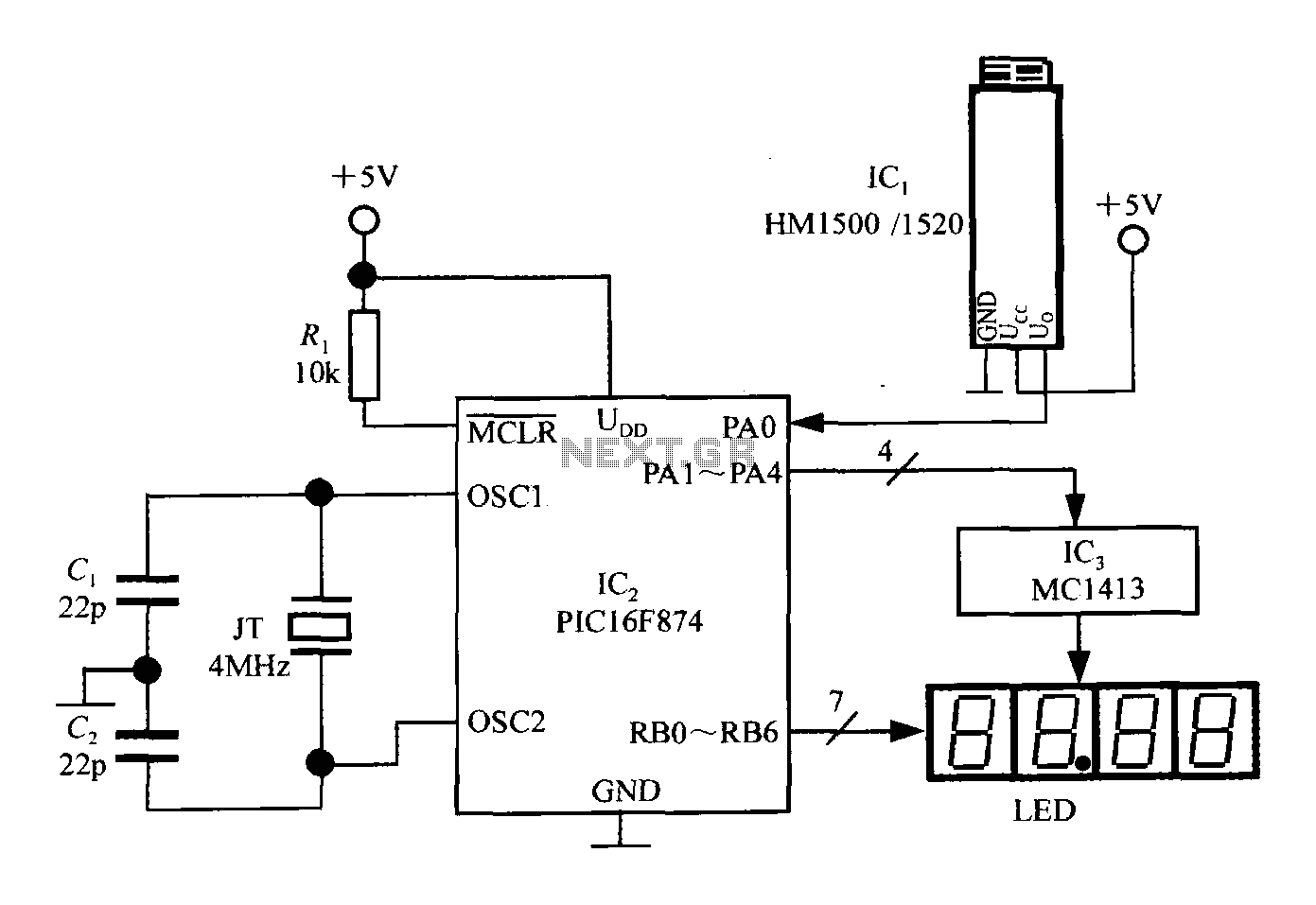
An intelligent humidity meter circuit utilizing the HM1500/1520 humidity sensor and a microcontroller configuration. The circuit operates on a +5V power supply and incorporates four common cathode LED digital displays. It employs three integrated circuits: IC1 is the HM1500/1520...