
Curtain ControlCircuit Based On The 555 IC
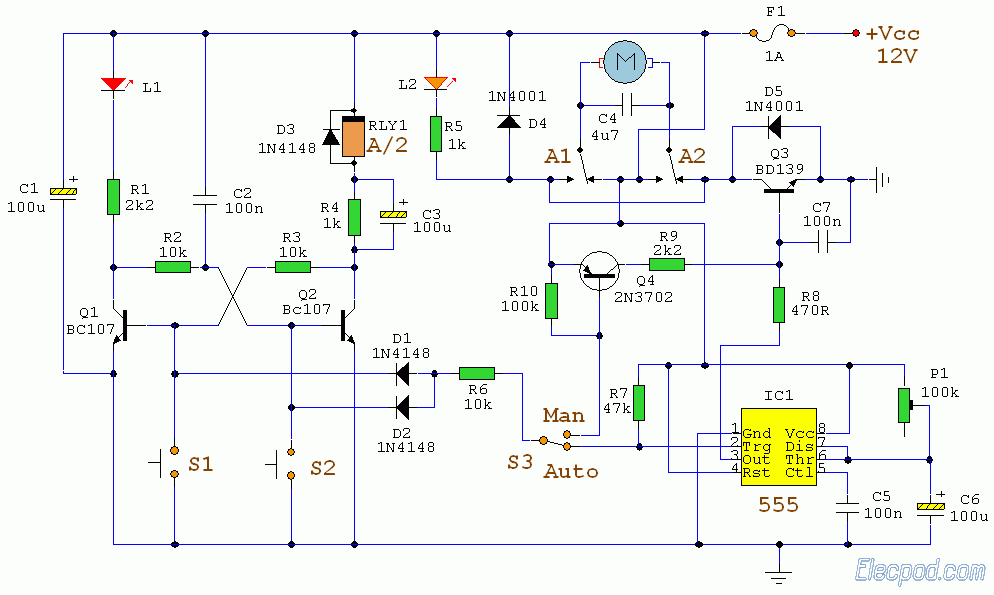
The curtain control circuit utilizes the 555 timer IC configured in monostable mode, allowing for precise control over the opening and closing of curtains. The circuit typically consists of a power supply, the 555 timer, a relay, and a switch for manual operation.
The power supply provides the necessary voltage to the circuit, usually in the range of 5V to 15V, depending on the specifications of the 555 IC and the relay used. The 555 timer is the central component, which generates a pulse when triggered by the manual switch.
The switch, when pressed, sends a trigger signal to the 555 timer, initiating the timing cycle. The duration of the pulse can be adjusted by changing the resistor and capacitor values connected to the timer. This timing determines how long the relay is activated, thus controlling the motor that opens or closes the curtains.
The relay acts as a switch that controls the motor's power supply. When the relay is energized by the output from the 555 timer, it closes the circuit to the motor, allowing it to operate and move the curtains. A diode may be included in parallel with the relay coil to prevent back EMF from damaging the 555 timer when the relay is deactivated.
This circuit can be enhanced with additional features such as a light sensor for automatic operation based on ambient light levels, or a remote control interface for added convenience. Overall, the curtain control circuit based on the 555 IC provides an effective solution for automated curtain management.The following circuit shows about Curtain Control Circuit Diagram. This circuit based on the 555 IC. Features: Switch for manual control, IC and a .. 🔗 External reference
Related Circuits
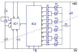
The following circuit illustrates an LED Knight Rider Circuit Diagram. This circuit is based on the 4017 and 555 integrated circuits. Features include the Knight Rider effect with four LEDs. The LED Knight Rider circuit is designed to create a...
Can anyone inform me whether the output of a monostable 555 timer circuit can be utilized to trigger another similar timer circuit? I have illustrated my concept with a... The monostable 555 timer circuit is a versatile component widely used...
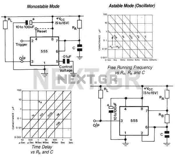
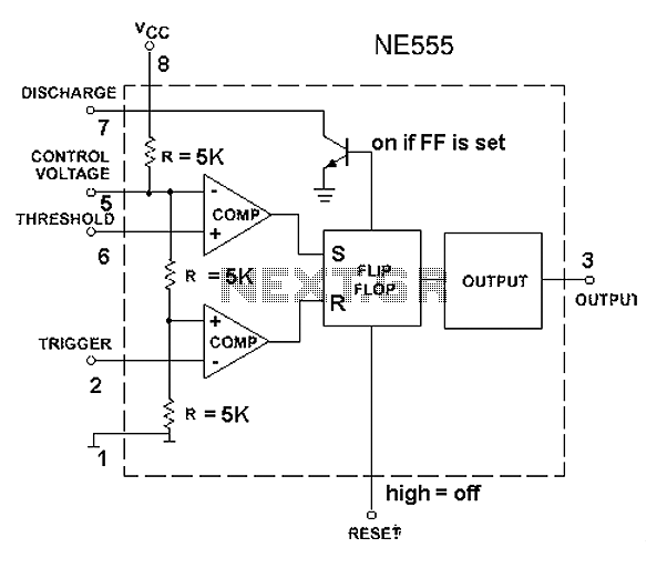
The 555 is a highly stable device for generating accurate time delays or oscillation. Additional terminals are provided for triggering or resetting if desired. In the time delay (monostable) mode of operation, the time is precisely controlled by one...
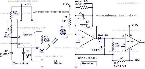
All components used in the Moving Sensor/Detector Schematic Diagram utilize the IC NE555 and the Phototransistor L14F. The primary component in this circuit is the IC NE555, along with an IR LED, the Phototransistor L14F, and the IC LM1458....
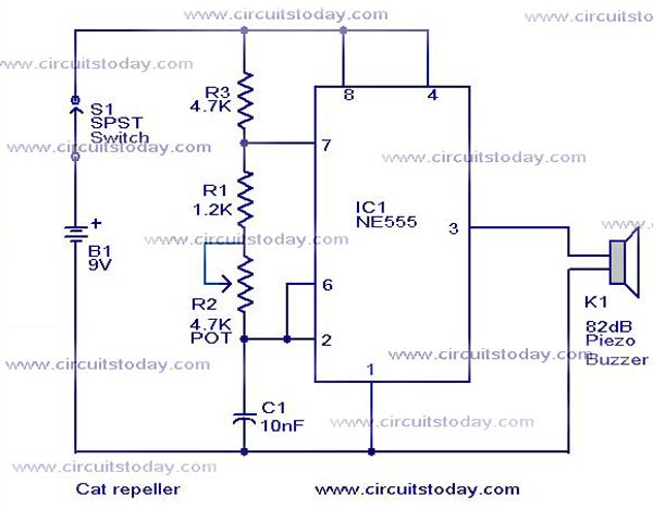
This cat and dog repeller circuit is designed to deter animals from specific areas. The circuit utilizes ultrasonic sound, which is known to provoke a strong response in many animals, particularly cats. The design features an astable multivibrator configuration...
The 555 timer circuit, regardless of the manufacturer, has a consistent internal structure and performance. Various manufacturers produce different models of the 555 timer, including MC555, CA555, XR555, LM555, as well as domestic models like SL555, FX555, and 5G1555....