
buzzer circuit
The NE555 timer IC is configured in an astable mode, allowing it to function as an oscillator that generates a square wave output. In this configuration, the frequency of the oscillation is determined by the resistors and capacitors connected to the timer. The 1K variable resistor serves as a means to fine-tune the frequency, while the 15K resistor sets a baseline resistance that contributes to the timing cycle.
To implement this circuit, the following connections are essential: pin 1 (ground) is connected to the negative terminal of the power supply, while pin 8 (VCC) is connected to the positive terminal of the 9-volt supply. Pins 2 (trigger) and 6 (threshold) are interconnected, and pin 2 is also connected to the junction of the 1K variable resistor and the 15K resistor, which are arranged in series with the capacitor connected to pin 6. The capacitor, typically a non-polarized type, is connected between pin 6 and ground, influencing the timing characteristics of the output.
Pin 3 (output) is connected to the positive terminal of the speaker, while the negative terminal of the speaker is grounded. The output from the NE555 will drive the speaker, producing the desired buzzer sound. To ensure reliable operation, it is advisable to use electrolytic capacitors rated for at least 10 volts to prevent damage from voltage spikes. The choice of speaker impedance between 8 to 25 ohms will affect the loudness and quality of the sound produced.
This circuit can be further enhanced by integrating additional components, such as diodes for protection against back EMF generated by the speaker, or additional resistors and capacitors to modify the sound characteristics. Other configurations, such as the 555 tone generator and siren circuit, can also be explored for varied audio output applications.This is a project of a 555 buzzer circuit. NE555 is a timer IC comes in 8 pin dip package, it performs wide variety of tasks in electronic circuits. The circuit mentioned below will produce a buzzer sound when 9 volt power will be applied. The frequency of sound can be changed with the help of 1K variable resistor and changing the value of 15K res
istor. All electrolytic capacitors will be of 10 volt ratings, use 8 to 25 ohms speaker. There are also other circuits which you can use for buzzer purpose like 555 tone generator and siren circuit. 🔗 External reference
Related Circuits
This active subwoofer filter circuit is a 24 dB per octave filter with a Bessel characteristic and a cutoff frequency of 200 Hz. It is suitable for those experimenting with audio circuits in the subwoofer range, as all audio...
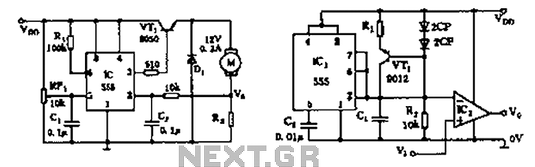
The circuit consists of a 555 motor automatic governor configuration. It includes flip-flops, a 555 timer, and a switching tube. A sampling circuit is formed by connecting R7 and the motor in series. RP1 is used to control the...
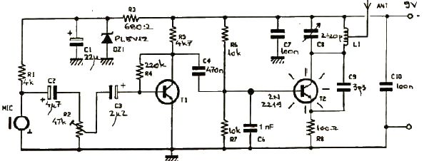
This FM transmitter electronic project operates in the FM band with a transmission power of approximately 250 mW. The circuit is straightforward and utilizes common transistors and electronic components. The T1 transistor, which may be a BC107, BC171, or...
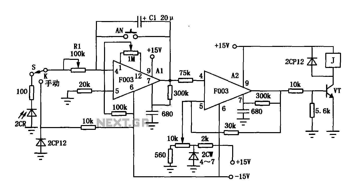
The F003 circuit is a versatile photographic component that functions as an operational amplifier amplifying automatic timer circuit. The operational amplifier A1 serves as an integrator, while operational amplifier A2 is configured as a comparator. A 2CR silicon photocell...
A simple test circuit designed for troubleshooting audio and radio equipment. It can inject a square wave signal rich in harmonics or be used with headphones as an audio tracer. A single-pole double-throw switch is utilized to toggle between...
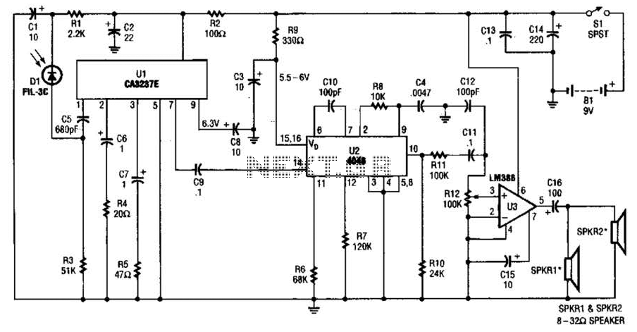
The infrared (IR) detector diode D1 captures the IR signal at approximately 40 kHz and transmits it to U1, a high-gain preamplifier, which then sends the signal to U2, a 4046 phase-locked loop (PLL) configured as a frequency modulation...