
Automatic Garage / Shed Alarm

This single-zone burglar alarm circuit is designed to provide basic security with user-friendly features. The system operates using a low-power design, making it suitable for battery operation, which is particularly advantageous in locations without access to mains electricity. The circuit is powered by a voltage source that can range from 5 to 15 volts, allowing flexibility in component selection based on availability and application requirements.
The core functionality of the alarm relies on a relay that is activated when the designated entry and exit procedures are not followed correctly. The use of normally-closed input devices ensures that any unauthorized access triggers the alarm. The integration of a green LED provides a visual indication of the system status, enhancing user interaction and feedback.
To customize the delay times, the circuit incorporates adjustable resistors R5 and R6. This feature allows users to tailor the alarm's response times to their specific needs, accommodating various entry and exit scenarios. The circuit's design also includes a straightforward setting mechanism via switch SW1, simplifying the process of arming and disarming the system.
In addition to its primary function, the circuit can be modified to include a siren cut-off timer, which can enhance the system's usability in certain environments. The support material provided with the alarm circuit ensures that users can effectively construct and troubleshoot the system, making it accessible even for those with limited electronics experience.
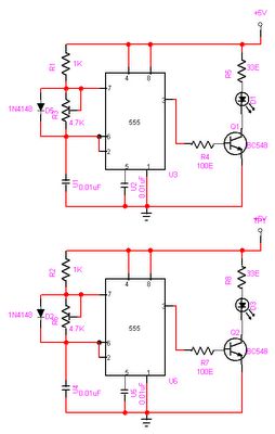
Overall, this burglar alarm circuit exemplifies a practical solution for enhancing security in a variety of settings, combining ease of use with customizable features to meet diverse user requirements.This is a simple single-zone burglar alarm. The basic design includes automatic Exit and Entry delays. It doesn`t include a siren cut-off timer. But with A Small Modification - you can add one to the circuit. The alarm will accept the usual types of normally-closed input devices such as - magnetic-reed contacts - micro switches - foil tape - and P IRs. It has an extremely small standby current - making it ideal for battery-powered operation. This is particularly useful where your garage/shed has no mains supply. I`ve used a 9-volt battery in the diagram, but the circuit will work at anything from 5 to 15-volts. Just choose a Relay and Siren that are suitable for the voltage you want to use. It`s easy to use. To set the alarm move SW1 to the "set" position. You now have about 10 to 15 seconds to leave the building. When you return and open the door - the green LED will light. You then have about 10 to 15 seconds to move SW1 to the "off" position. If you fail to do so - the relay will energize and the Siren will sound. Of course - you can turn the Siren off at any time by moving SW1 to the "off" position. Because of manufacturing tolerances - the precise length of any delay depends on the characteristics of the actual components you`ve used in your circuit. But by altering the values of R5 & R6 you can adjust the Exit and Entry times to suit your requirements.
Increasing the values increases the time - and vice-versa. The Support Material for this alarm includes a detailed circuit description - a circuit simulation - a parts list - a step-by-step guide to construction - and more. 🔗 External reference
Related Circuits

An automatic reclosing PLC control program has been developed based on the specifications for automatic reclosing devices and PLC I/O definitions. The design includes a ladder-shaped diagram with the following features: 1) When the circuit breaker closes, the K4...

This circuit is capable of generating up to 1 W of audio power to drive a speaker or horn. When the CDS cell is exposed to light, its resistance decreases, activating NOR gate (a). This activation causes gates (a)...

This simple alarm circuit utilizes a single integrated circuit (IC) and a driver transistor, allowing the use of either normally open (NO) or normally closed (NC) sensors. When a sensor is triggered, the input to U1A transitions to a...

When running large-scale software or games, a computer's internal temperature can increase significantly, especially during hot summer months. Although the machine is equipped with a CPU and graphics card fan, poor hot air circulation prevents immediate removal of heat...

This is a simple alarm circuit that produces a musical tone when water or any conductive liquid comes into contact with the two sensor wires provided. The circuit utilizes four transistors and one melody generator IC (M3482). When water...
The objective of this project is to create a controller-based model that counts the number of individuals entering a specific room and activates the lighting accordingly. This is achieved through the use of sensors that detect the current number...
Warning: include(partials/cookie-banner.php): Failed to open stream: Permission denied in /var/www/html/nextgr/view-circuit.php on line 713
Warning: include(): Failed opening 'partials/cookie-banner.php' for inclusion (include_path='.:/usr/share/php') in /var/www/html/nextgr/view-circuit.php on line 713