
Automatic reclosing device program Control Ladder

This case study addresses the limitations of traditional automatic reclosing relay systems by introducing a PLC-based design for automatic reclosing. The hardware implementation features straightforward and reliable wiring, while the software not only fulfills the control functions of the automatic reclosing device but also integrates PLC counters, timers, and other instructions. This design allows for the adjustment of delay times and the automatic resetting of the system, enhancing the control and flexibility of the pump system, and demonstrating versatility and practicality in operation. The overall architecture provides a robust solution for managing circuit breaker operations with a focus on safety, reliability, and responsiveness to operational conditions. Automatic reclosing PLC control program designed according to the Control of automatic reclosing device and the PLC I/o definition, design ladder -shaped diagram as follows: 1) when the circuit breaker closing, K4 control switch is turned on, its contact point is closed 00004. DL Liha breaker auxiliary contacts, the normally closed contact 00000 disconnected. When the line fails, the circuit breaker jump gates, auxiliary contacts DL F-off, the normally closed contact is closed 00000, 20003 coil is energized, the normally closed contacts are closed, the timer TIMOOO work.
After a delay. 01001 coil is energized and closing. 2) If the automatic reclosing successful closing by the delay TIMO01, the normally closed contacts TIMO01 disconnect line power ring 20004, 20004 closes its normally closed contact, automatic reclosing devices automatically reset. 3) If the closing is not successful, complete reclosing predetermined times after the number 20003 coil is energized, due to the delay TIMO01 make with coil 20004 is still energized, the normally closed contact 20004 is broken open state, coil break 20003 Electricity.
And because a circuit breaker trip state where the normally closed contact 00000 closed, self-holding role to play, so that the coil has been energized 20004, reclosing can not be achieved again. 4) the operation control switch K is turned on so that the node K4. 20004 coil is energized, for manual reset. 5) Ladder instruction selection counter CNT is set from reclosing predetermined number of times coincide, TIMOOO automatic coincidence gate resistance movements extended time.
TIMO01 automatic reclosing reset time. By the rising and falling edges of the differential instruction DIFU differential (13) and DIFU (14) and the timer instruction TIM002 combination, to achieve a delay counter CNT is reset to ensure autoreclosure complete the required number of times coincide. 6) manually operated circuit breaker trip process, Kl, K2 is turned on, the respective normally closed contacts open 00001,00002 ensure coil 20003 is not energized, the automatic reclosing lockout circuit.
7) manually operated circuit breaker trip process. K3 connected to the normally closed contact 00003 off, reclosing lockout circuit. 00003 normally open contacts closed, the coil is energized 01002, turn accelerated relay trip circuit. 8) When the circuit breaker or insufficient hydraulic pressure, SQ1,9Q2 switch can not be pressed together, the normally open contact 00005 open, automatic reclosing lockout circuit.
Normally closed contact 00006 closes, 01000 electric coil, connected in series in the trip circuit contacts open, the latch trip circuit. (4) Conclusion This case study of the traditional automatic reclosing relay apparatus shortcomings exist, PLC-based design of automatic reclosing.
The design, the hardware has installed wiring is simple, reliable; on the software, not only to meet the group automatic reclosing device of this control function, but also the application of PLC counters, timers and other instructions to achieve automatic reclosing overlap times required to adjust the delay time and automatically reset the system to improve the control and flexibility of the pump system has the versatility and practicality.
Related Circuits
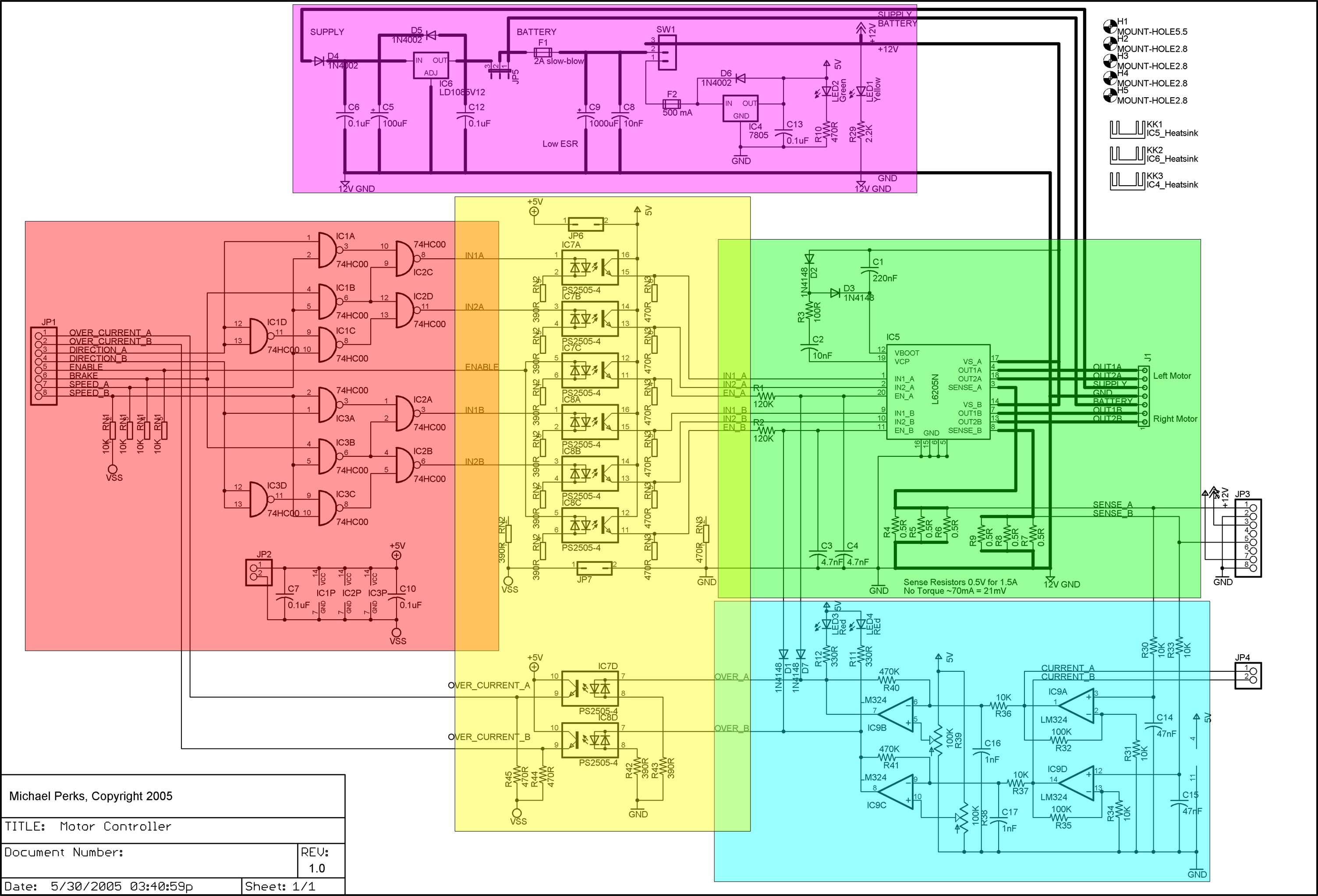
A dual DC motor controller employs an H-bridge controller chip. In addition to the standard features of the H-bridge driver chip, such as thermal and over-current protection, the circuit supports dual 12V/5V regulated power supplies, sign/magnitude and brake driver...
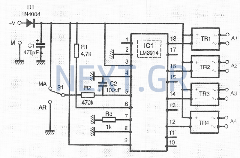
It is common to require the sequential powering of devices, which can involve managing numerous switches that are often in hard-to-reach locations, particularly for informational devices and their connections. This sequential actuator autonomously activates one to four devices in...
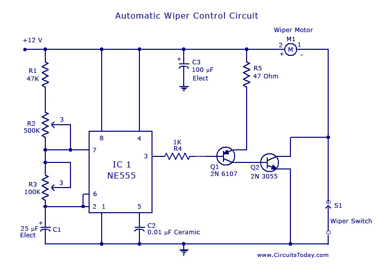
A circuit for car windshield/wiper motor speed control built using an NE 555 IC. This enables intermittent windshield wiper control, which changes the sweep rate to 10 seconds. The circuit utilizes the NE 555 timer IC configured in astable mode...
Some time ago, a media center box was created to replace a DVD player, satellite receiver, VCR, and PlayStation 2 with a single device. A Core 2 Duo processor system successfully replaced all these electronic devices. However, a remote...
This audio mixer circuit schematic is designed around four current-controlled amplifiers, all integrated within the SSM2024 IC. The audio mixer circuit utilizes the SSM2024 integrated circuit, which features low-noise, high-performance operational amplifiers suitable for audio applications. The SSM2024 is particularly...
Efficient automatic solar garden lights circuit with minimal components. The advantage is that it operates completely automatically, with the solar panel serving as a light detector. The efficient automatic solar garden lights circuit is designed to provide illumination using renewable...