
Automatic Headlight Brightness Switchs

The circuit operates by utilizing a light sensor, typically a phototransistor or photodiode, which detects the presence of oncoming headlights. When the sensor detects a certain light level, it triggers a relay or a transistor switch that changes the state of the headlight beam from high to low, ensuring compliance with traffic regulations and enhancing safety.
The primary components of this circuit include a power supply, the light sensor, a relay or transistor, and the headlight switch. The light sensor is positioned in such a way that it can effectively receive light signals from oncoming vehicles. When the ambient light from these headlights exceeds a predefined threshold, the sensor activates the relay. This relay is connected to the headlight circuit and switches the headlights from high beam to low beam.
In addition to the light sensor and relay, a resistor may be used to limit the current flowing through the sensor, ensuring its protection. A diode can also be implemented across the relay coil to prevent back EMF from damaging the circuit when the relay is deactivated. The circuit diagram typically illustrates the connections between these components, showcasing how they interrelate to perform the automatic switching function.
Overall, this automatic headlight switching circuit enhances driving safety by ensuring that high beams are only used when appropriate, thereby reducing glare for oncoming drivers. It serves as a practical application of basic electronic principles and can be a valuable addition to automotive lighting systems.This simple circuit can be wired into your headlight switch to provide automatic switching between high and low beam headlights when there is oncoming traffic. Simple electronics project with circuit diagram.. 🔗 External reference
Related Circuits

This is an automatic battery charger circuit that utilizes the LM324 integrated circuit, which enhances efficiency. It is capable of charging both 12V and 6V batteries, with filtration managed by switch S1. The circuit is designed to stop charging...
The humidifier circuit is based on a specific humidity sensor, Type NH-3 from Figaro. The circuit controls a ventilator that is part of an air humidifying system, depending on the sensor output. A triac is used to switch the...
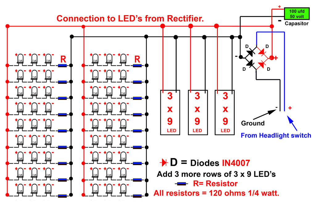
Gently bend the leads of the LEDs and, using the provided schematic circuit diagram, begin to solder. Once soldering is complete, it should... To successfully assemble the LED circuit, it is essential to follow a systematic approach. Start by preparing...
This circuit automatically activates a night lamp when the bedroom light is turned off. The lamp stays illuminated until the light sensor detects daylight in the morning. A super-bright white LED is utilized as the night lamp, providing bright...
Lamp dimmer. The circuit illustrated below can be employed for dimming lamps. It utilizes a minimal number of components, which can be conveniently installed within the lamp socket. This circuit is typically utilized in RC phase shift configurations. The...

This project is a digital Automatic Gain Control (AGC) system using a PIC16F876 MCU. The ability to set the gain level in a circuit and have it control itself is a very useful function. This circuit is a building...