
Automatic Headlight Reminder
This headlights reminder circuit offers a practical solution for older vehicles lacking an automatic lights-on warning system. The design leverages the 555 timer's astable mode to create a reliable timing mechanism, producing a continuous output that is instrumental in driving the 4017B decade counter. The integration of two ICs allows for efficient operation and a compact design.
The 555 timer (IC1) operates in astable mode, generating a square wave signal that toggles between high and low states. This oscillation is pivotal for clocking the 4017B counter (IC2), which sequentially activates the connected LEDs. The use of a decade counter enables the circuit to light up multiple LEDs in a specific sequence, enhancing user awareness of the lights being left on.
Transistor Q1 acts as a switch controlled by the ignition state. When the ignition is on, Q1 remains in the conducting state, effectively resetting the 555 timer and preventing the alarm from activating. This design ensures that the circuit is inactive during normal vehicle operation, preserving battery life. Upon turning off the ignition, Q1 deactivates, allowing the 555 timer to oscillate and trigger the alarm sequence.
The piezo siren provides an audible alert, while the sequential lighting of the LEDs serves as a visual reminder. The circuit's design allows for customization, including the option to use different colored LEDs for enhanced visibility or aesthetic appeal. Additionally, the optional diode D1 can be utilized to fine-tune the frequency of the 555 timer, enabling adjustments to the timing of the LED sequence.
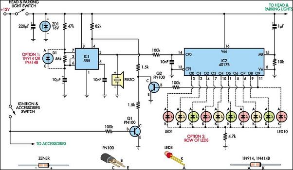
In summary, this headlights reminder circuit is a sophisticated yet practical solution for preventing battery drain in older vehicles. Its design is versatile, allowing for customization and ensuring effective operation through the integration of low-cost components.Do you drive an older car without an automatic "lights-on" warning circuit If so, you`ve probably accidentally left the lights on and flattened the battery on one or more occasions. This headlights reminder circuit will prevent that. It`s more complicated than other circuits but it`s also more versatile. As shown, the circuit uses two low-cost IC s. IC1 is a 555 timer which is wired to operate in astable mode. Its output clocks IC2, a 4017B decade counter. IC2 in turn drives a row of indicator LEDs and also resets IC1 (after about 10s) via transistor Q2. when the ignition is on, transistor Q1 is also on and this pulls pin 4 of IC1 low. As a result, IC1 is held reset and no clock pulses are fed to IC2. Conversely, if the ignition is turned off, Q1 will turn off and so IC1 will start oscillating and sound the piezo siren. At the same time, IC1 will clock IC2 and so LEDs 1-10 will light in sequence and stop (after about 10s) with the last LED (LED10) remaining on.
That`s because, when IC2`s O9 output (ie, pin 11) goes high, Q2 also turns on and this pulls pin 4 of IC1 low, thus stopping the oscillator (and the siren). That different colored LEDs are used to make the display look eye-catching but you make all LEDs the same color if you wish.
Installing optional diode D1 will alter IC1`s frequency and this will alter the display rate. Finally, if the lights are turned off and then back on again, the alarm will automatically retrigger. LED1 is always on if the lights are turned on. If you don`t want the LED display, just leave the LEDs out. 🔗 External reference
Related Circuits
The automatic sprinkler controller circuit consists of a +12 V power supply circuit, a light control circuit, and an irrigation control circuit, as illustrated in the accompanying figure. The +12 V power supply circuit includes a knife switch (Q),...
Model railroad turnouts, often referred to as switches, can be controlled in various ways. The simplest method is manual control, operated by hand. Remote activation is typically achieved through pneumatic (air) or electrical means. The project discussed in these...
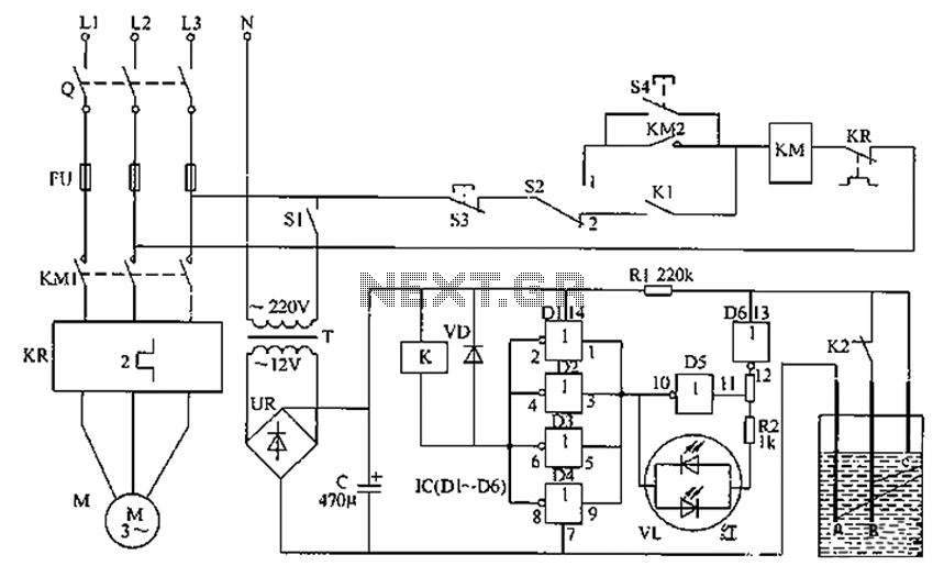
The liquid level automatic controller circuit consists of a power circuit, a control instruction level detection circuit, and a starter control circuit. The power circuit is formed by a power transformer, a rectifier bridge, and a filter capacitor. The...
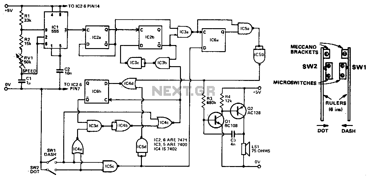
Automatically generated dits and dahs are produced over a speed range of 11 to 39 wpm. The upper limit can be raised by decreasing R2. SW1 and SW2 can be a "homebrew" paddle operated key. The described circuit is designed...
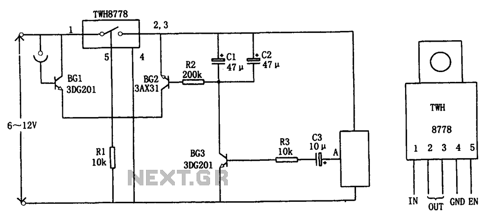
The circuit illustrated in FIG X pertains to automatic circuitry for US recorders. It primarily utilizes a new power switching device, TWH8778, which simplifies the design and eliminates the need for extensive debugging. The TWH8778's configuration and pin functions...
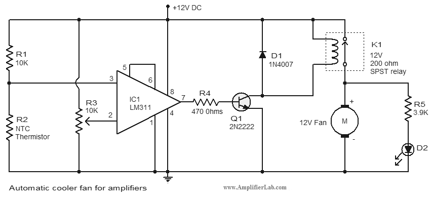
An automatic cooler fan for amplifiers is a circuit designed to conserve power in amplifier circuits. This circuit activates the fan. The automatic cooler fan circuit for amplifiers operates by utilizing temperature sensors to monitor the heat generated by the...
Warning: include(partials/cookie-banner.php): Failed to open stream: Permission denied in /var/www/html/nextgr/view-circuit.php on line 713
Warning: include(): Failed opening 'partials/cookie-banner.php' for inclusion (include_path='.:/usr/share/php') in /var/www/html/nextgr/view-circuit.php on line 713