
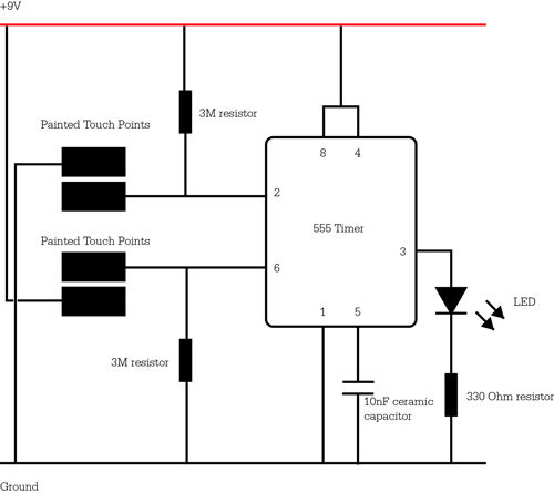
Automatic interval timer circuit composed of PUT
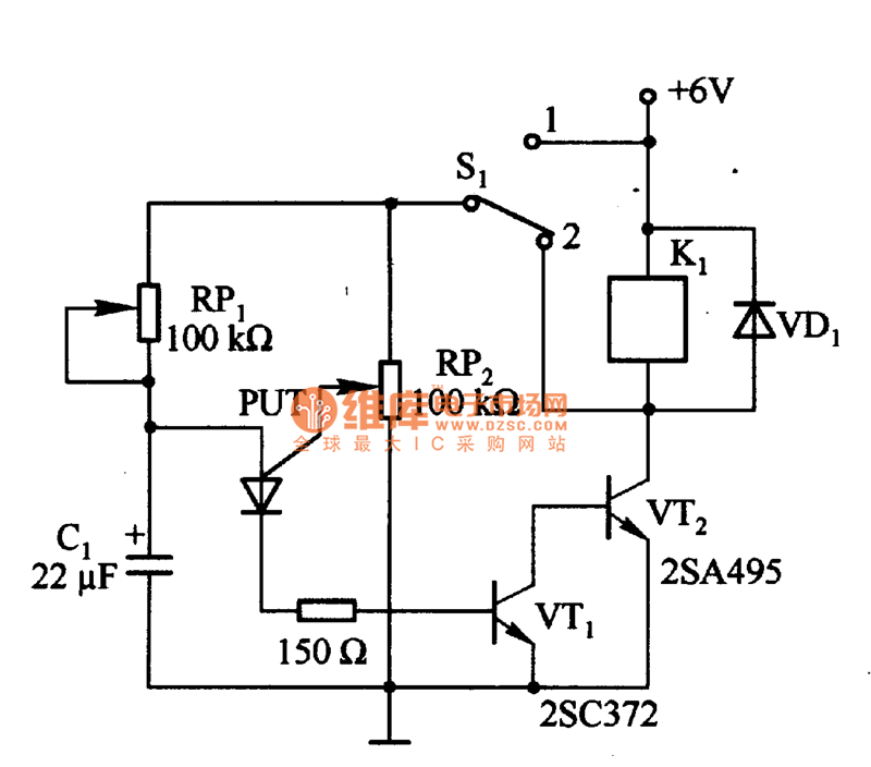
The circuit utilizes a Programmable Unijunction Transistor (PUT) as the primary oscillating component, which is known for its precise timing capabilities. The PUT is configured to generate a square wave output that can be used for various timing applications. The automatic interval timer circuit is designed to allow users to select between two modes of operation through the use of a single-pole double-throw (SPDT) switch, S1.
In automatic timing mode 1, the circuit is set to provide a predetermined time interval for automatic operations, such as activating a relay or controlling a motor. This mode is particularly useful in applications that require repetitive actions without user intervention. The timing duration can be adjusted by varying the values of the timing components, including resistors and capacitors in the circuit.
In contrast, the interval timing mode allows for manual control over the timing intervals. This mode is activated when S1 is switched to position 2. In this configuration, the circuit can be used for applications where precise control over timing is essential, such as in pulse generation or signal modulation.
The component RP2 plays a critical role in the circuit's operation. It is a variable resistor that allows for fine-tuning of the timing intervals. If the resistance value of RP2 is too large, it can limit the anode current flowing into the PUT, potentially causing the oscillator to fail to operate correctly. This highlights the importance of selecting appropriate resistance values to ensure reliable circuit performance.
Overall, this circuit design demonstrates versatility in timing applications, allowing users to switch between automatic and manual modes efficiently. Proper understanding and adjustment of the circuit components are essential for achieving the desired timing characteristics in various electronic applications.Figure 1 is composed of the PUT and other automatic interval timer circuit. In the circuit, PUT is the oscillator. Using the switch S1 to switchover the interval time and automatic time. When S1 connects to 1, it is automatic timing mode 1, thenS1connects to2, itis the interval time. If the resistance of RP2is too large, PUT anode current is less than the.. 🔗 External reference
Related Circuits
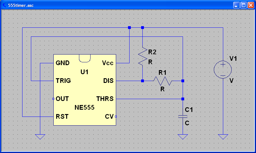
ECEN 2250 myDAQ Experiment Capacitors and the 555 Timer. The experiment involving capacitors and the 555 timer within the ECEN 2250 myDAQ framework focuses on understanding the behavior of capacitors in electronic circuits and the functionality of the 555 timer...
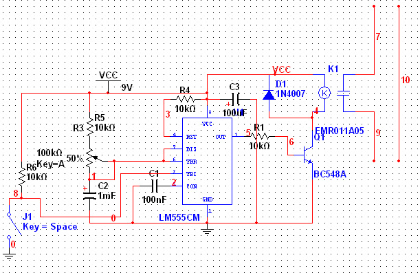
The 555 Timer has extensive applications in electronics. This document describes the use of the 555 Timer in a monostable multivibrator configuration to trigger a transistor driver that energizes a relay, which in turn operates a 230V AC lamp...
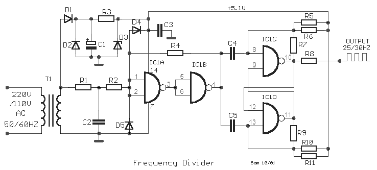
This is a classic frequency divider by two, implemented using a T-flip flop circuit, specifically with IC1 [4011]. In this circuit, the frequency from the network, after limiting the negative half-period of the sine wave and transforming it into...
Ensure that connections are verified against the circuit diagram and schematic provided below. This can be utilized while following the tutorial video. The circuit diagram serves as a crucial reference for accurately assembling electronic components in a project. It illustrates...
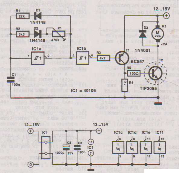
This PWM controller circuit is suitable for managing small motors with a maximum current consumption of 2A. For higher currents, additional cooling is required. The PWM (Pulse Width Modulation) controller circuit is designed to efficiently control the speed of small...
555 timer circuits LM555 - Astable Oscillator Calculator, Capacitor Calculator, Basic Circuits for the LM555 Timer, Triggering and Timing Helpers for Monostable Timers, Controlling Circuits for LM555 Timers, Advanced Circuits for the LM555 Timer, LM556 Timers with Complementary or...