
Touch Sensitive On/Off Circuit 555 Timer
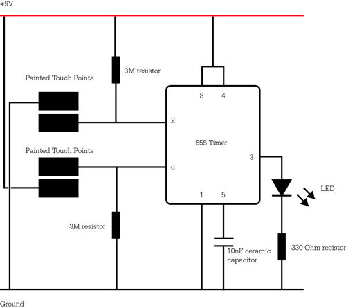
The circuit diagram serves as a crucial reference for accurately assembling electronic components in a project. It illustrates the arrangement and interconnections of various elements such as resistors, capacitors, diodes, and integrated circuits. Each component is typically represented by standardized symbols, allowing for easy identification.
In this case, the schematic includes detailed annotations indicating the values of components, such as resistance in ohms or capacitance in farads, along with the power supply specifications. The layout may also highlight the paths for current flow, ensuring that the user can trace the circuit effectively.
When following the tutorial video, it is imperative to cross-reference the diagram at each step of the assembly process. This practice minimizes the risk of errors, such as incorrect connections or component placements, which could lead to malfunction or damage to the circuit.
Additionally, attention should be given to the orientation of polarized components, such as electrolytic capacitors and diodes, as incorrect placements can result in circuit failure. Proper grounding techniques should also be observed, ensuring that all grounds are connected to a common point to avoid noise and interference.
In summary, utilizing the circuit diagram and schematic as a guide while assembling the project is essential for achieving a functional and reliable electronic circuit.Make sure to double-check your connections using the circuit diagram and schematic below. You can use this while you follow along in the tutorial vide.. 🔗 External reference
Related Circuits
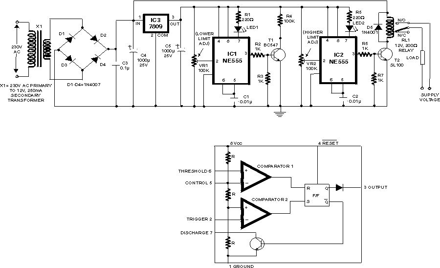
This over/under voltage cut-out will save your costly electrical and electronic appliances from the adverse effects of very high and very low mains voltages. The circuit features auto reset and utilises easily available components. It makes use of the...
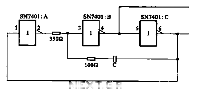
The clock signal generating circuit utilizes an RC configuration, commonly applicable in most TTL systems. This circuit requires a set of six inverters, specifically three inverters from the SN7401 series. The clock frequency is determined by the values of...
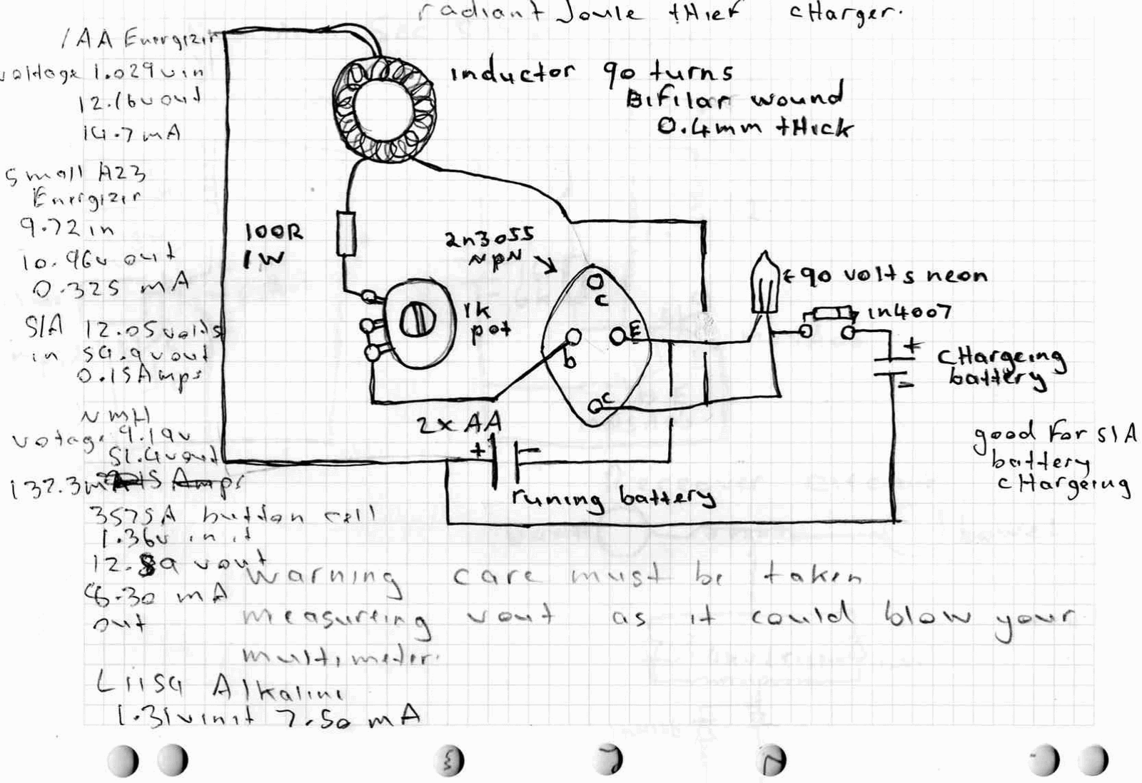
A high power joule thief circuit is explained in this post, which can be constructed by any new hobbyist. Here is the simplified drawing of the radiant joule thief battery charger. The inductor was wound with many turns until...
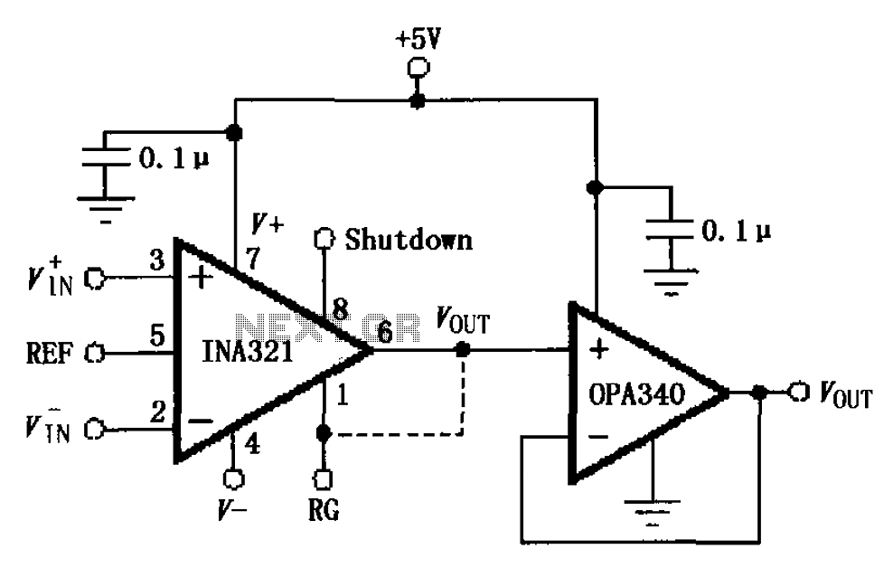
The circuit depicted in the figure consists of an OPA340 operational amplifier configured as a voltage follower, serving as an output buffer for the INA321/322 output. The optimal load impedance for the INA321/322 is 10k ohms or greater. A...
This circuit is a constant current protection type that limits the output current to a specific value in cases of over-current and short-circuit conditions. When the output current exceeds this limit, the output voltage decreases. The CW200 power management...

A CMOS gate and transistor buffer can be used as an effective driver for a piezoelectric transducer. The use of a CMOS gate combined with a transistor buffer offers a robust solution for driving piezoelectric transducers. CMOS technology, known for...
Warning: include(partials/cookie-banner.php): Failed to open stream: Permission denied in /var/www/html/nextgr/view-circuit.php on line 713
Warning: include(): Failed opening 'partials/cookie-banner.php' for inclusion (include_path='.:/usr/share/php') in /var/www/html/nextgr/view-circuit.php on line 713