
Circuit Design And Technology
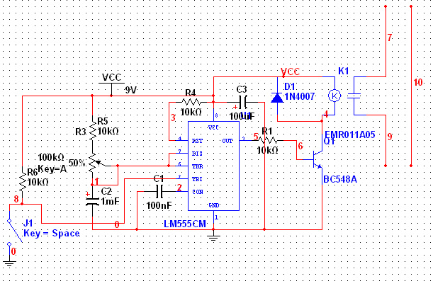
The 555 Timer is a versatile integrated circuit widely used for timing, pulse generation, and oscillation. In this application, it is configured as a monostable multivibrator, which produces a single output pulse when triggered. The monostable configuration is achieved by connecting Pin 6 (threshold) and Pin 7 (discharge) together, which allows the timer to be reset and triggered effectively.
The resistor-capacitor (RC) network at Pin 4 (reset) plays a critical role in stabilizing the timer's operation. The 10kΩ resistor limits the current to ensure that the capacitor charges slowly, preventing any unintended triggering at power-up. The 100µF capacitor provides a delay that allows the circuit to stabilize before the timer is activated.
The combination of a 100kΩ variable resistor and a 10kΩ fixed resistor connected to Pin 7 allows for fine-tuning of the timing interval while maintaining a safe operating condition. The capacitor connected from Pin 7 to ground further enhances the timing characteristics by controlling the discharge path.
The trigger input at Pin 2 is designed to be kept high to avoid floating, which could lead to erratic behavior. The inclusion of a push button switch allows for manual triggering of the timer, initiating the pulse that will energize the relay.
The transistor functions as a switch in this circuit. When the output from the 555 Timer goes high, it forward biases the Base-Emitter junction of the transistor, allowing current to flow from the collector to the emitter. This action energizes the relay coil, closing the normally open contact and allowing the AC lamp to be powered on.
To protect the transistor from damage due to back EMF generated by the relay coil when it de-energizes, a diode is connected in parallel with the relay coil. This diode provides a path for the inductive kickback, ensuring that the transistor remains unharmed.
The final output of the circuit is the AC lamp, which is connected in series with the relay's normally open contact. When the relay is activated, the lamp is powered by the live AC source, completing the circuit and illuminating the lamp. This configuration demonstrates the practical application of the 555 Timer in controlling high voltage devices through low voltage signals.555-Timer has vast application in electronics. In my recent post I showed you other forms in which a 555-Timer could be applied. Today, we shall use 555-Timer in a Monostable Multivibrator configuration to trigger a Driver (Transistor) in energizing a relay and in turn operate a lamp of 230V AC when the relay normally open contact is energized. Ab ove shows a configuration of a 555-Timer connected in a monostable pattern. This is achieved by connecting Pin 6 and Pin 7 together (bridged using a jumper). Then, connect Pin 8 to the supply rail (power supply line). Then, connect a 10k © resistor from pin 4 to the supply rail and then, also connect a capacitor (electrolytic capacitor) of 100 µF 16v from that same pin 4 to ground (0v or neutral line of the power supply). The essence of the resistor capacitor network at pin 4 is to slow down or stop immediate start up of voltage at pin 4 when the power source is turn On initially.
This will eliminate false triggering of the 555-Timer from operating the Lamp when we didn`t even intend for nit to be operated. Now, from pin 7, connect a resistor of 100k © variable resistor in series with a 10k © fixed resistor to the supply rail (power supply line).
That is to say that, the two resistors will be in series and one of its terminals will be connected to pin 7 and the other terminal will be connected to supply rail. The fixed resistor is to ensure that the variable resistor when adjusted to 0 © will not affect the circuit in anyway.
And now, connect a 1000 µF 16v capacitor from pin 7 or pin 6 to ground (negative rail or neutral line of the power source). Lastly in regard to the first stage, connect a resistor of 10k © in series with pin 2 (Trigger Pin or Input) and the supply rail.
Then, connect a push button soft switch between pin 2 and ground (neutral rail). This is to keep the input to the 555-Timer IC High so as not to make it floating to avoid it been falsely triggered. This is the last stage if I might conclude from my perspective. This is just a transistor driver stage. It is simply a transistor connected to function as a switch. When its Base-Emitter junction is forward bias by the presence of a voltage from the output of the monostable multivibrator (555-Timer), it cause the electrons to migrate from the emitter to the collector thereby causing large amount of a current to flow through the relay thereby energizing the relay and its contact is therefore closed and thus, our lamp been connected in series with the relay-contacts is operated ON.
The resistor in series with the Base of the transistor is just to limit the amount of current flow into the Base of the transistor to a safe level not to damage the transistor or exceed its ratings. The relay coil terminal is connected in between the collector of the transistor and the supply rail. Note also, a diode has to be connected across the collector of the transistor and the supply rail. This is to eliminate any back-emf that might be produce by the relay coil when it de-energizes thereby damaging the transistor.
Finally, the Lamp (AC Bulb) is then connector in series with the normally-Open contact of the relay and the other terminal goes to the Live connection of the AC Source. Then the other terminal goes to the Neutral Line of the AC Source. 🔗 External reference
Related Circuits
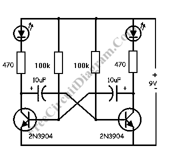
This LED flasher circuit is a classic two-transistor flip-flop. It is a popular circuit often built by beginners in electronic circuit design. The schematic diagram of this well-known LED flasher circuit consists of two transistors, two capacitors, four resistors,...
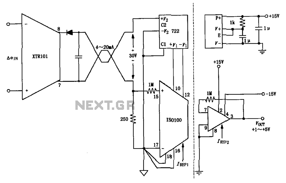
The circuit combines the XTR101 with the ISO100 isolation amplifier to transform a 4-20 mA current signal into a voltage output ranging from +1V to +5V while providing power supply isolation. It features excellent anti-jamming capabilities, making it suitable...
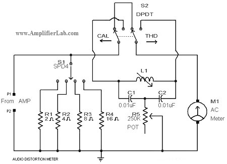
A circuit diagram of an audio distortion meter is presented here. An audio distortion meter is utilized to measure Total Harmonic Distortion (THD). The audio distortion meter is an essential tool in audio engineering, designed to quantify the level of...
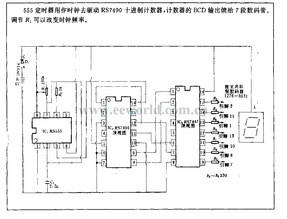
The 555 timer is utilized as a clock source to drive the RS7490 decimal counter, providing a BCD output to a 7-segment LED display. The clock frequency can be adjusted by changing the value of resistor R1. The circuit operates...
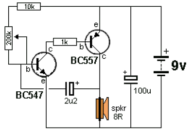
The ticking bomb sound generator circuit diagram operates by charging a 2.2 µF capacitor. When the voltage at the base of the NPN transistor reaches 0.65 V, it activates the transistor, which in turn activates the BC557 transistor, increasing...
A simple audio compressor is designed using the SSM2165 integrated circuit (IC). There is limited explanation available regarding the schematic of this compressor circuit; however, special attention should be given to the capacitor used. The audio compressor circuit utilizing the...