
Automatic Intruder Alarm
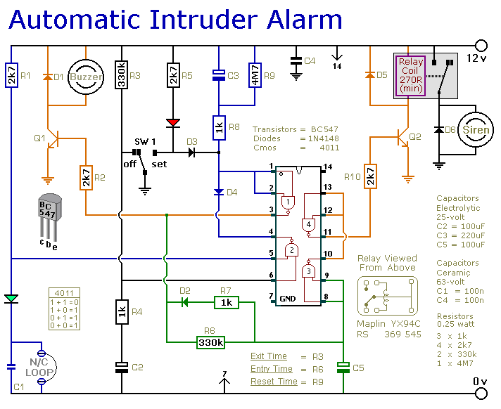
The described burglar alarm circuit operates within a single zone, intended to provide security for a confined area. The circuit features automatic exit and entry delays, which allow users to exit the premises without triggering the alarm immediately after activation. The timed bell or siren cut-off further enhances usability by preventing the alarm from sounding indefinitely, which can be beneficial in reducing false alarms or accidental triggering.
The circuit is compatible with various normally-closed input devices. Magnetic reed contacts are commonly used in door and window security, where the alarm is triggered when the contact is opened. Micro switches can be employed in various applications, such as detecting movement or the opening of a lid. Foil tape can serve as a flexible sensor along surfaces, while passive infrared sensors (PIRs) detect motion based on body heat.
For applications requiring normally-open triggering devices, such as pressure mats, the circuit can be modified accordingly. This flexibility allows the circuit to be tailored to different security needs and environments.
User operation is straightforward. Upon securing the premises, the user must verify that the green LED indicator is illuminated, confirming the system is ready. The switch SW1 is then moved to the "set" position, activating the alarm system. The red LED serves as a visual cue that the system is armed. The user is granted a grace period of approximately 30 seconds to exit the building before the alarm becomes fully operational.
Upon returning and opening a door, the circuit is designed to detect the interruption of the input device, triggering the alarm and alerting occupants or neighbors of a potential breach. This simple yet effective design ensures ease of use while providing essential security features.This is a simple single-zone burglar alarm circuit. Its features include automatic Exit and Entry delays and a timed Bell/Siren Cut-Off. It`s designed to be used with the usual types of normally-closed input devices such as - magnetic reed contacts - micro switches - foil tape - and PIRs. But it can be Easily Modified to accept normally-open triggering devices - such as pressure mats. It`s easy to use. First check that the building is secure and that the green LED is lit. Then move SW1 to the "set" position. The red LED will light. You now have about 30 seconds to leave the building. When you return and open the door - t 🔗 External reference
Related Circuits

After the power switch is activated, the motor does not start immediately but instead has a specified delay period. This setup allows the machine to perform automatic intermittent lubrication control. The circuit for the motor boot delay and intermittent...

This simple alarm circuit utilizes a single integrated circuit (IC) and a driver transistor, allowing the use of either normally open (NO) or normally closed (NC) sensors. When a sensor is triggered, the input to U1A transitions to a...

The following circuit illustrates the Ford Probe Single Wire Door Alarm System. This Single Door Locking Wire manages both LOCK and UNLOCK functions, indicating that the pulse wires must be connected to the same vehicle wire. The system primarily...

A CMOS logic gate is utilized in this circuit. When an object approaches the antenna, the change in oscillator output is detected by components 1)1 and 1)2, which is then amplified by U1C. This amplification drives Q1, activating alarm...

IC1 generates a pulse that modulates the 1000-Hz tone generated by IC2. This circuit can be used to generate warning or alert signals. The circuit described consists of two integrated circuits (ICs), where IC1 is responsible for generating a pulse...

Voltage regulator ICs (78xx series) deliver a stable output voltage despite a fluctuating input supply when the common terminal is grounded. Any voltage above zero volts (ground) connected to the common terminal is added to the output voltage, meaning...