
automatic garden light controller system
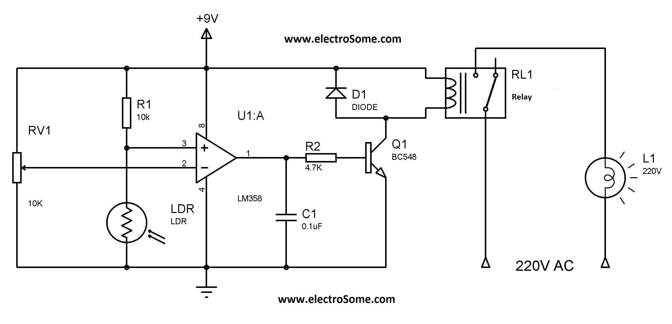
The circuit design is centered around the LM358 operational amplifier, which serves as a voltage comparator. The LDR is placed in a voltage divider configuration with a fixed resistor, allowing the output voltage at pin 3 to vary according to the light intensity. The 10K potentiometer allows for fine-tuning the reference voltage at pin 2, enabling customization of the light activation threshold.
When ambient light levels decrease, the resistance of the LDR increases, causing the voltage at pin 3 to rise above the reference voltage at pin 2. This transition causes the output of the LM358 to switch from low to high, activating the BC548 transistor. The transistor, functioning as a switch, allows current to flow through the relay coil, energizing the relay and turning on the connected street or garden lights.
The relay used in this circuit should be rated appropriately for the load it will control, ensuring safe operation. The circuit can be powered by a suitable DC power supply, with the LM358 and BC548 operating within their specified voltage and current ratings. By incorporating a diode in parallel with the relay coil, back EMF generated when the relay is deactivated can be safely dissipated, protecting the transistor from potential damage.
This automatic lighting control circuit is particularly beneficial for outdoor applications, providing convenience and energy savings by ensuring lights are only activated when necessary. The simplicity and low cost of the components make this design accessible for various practical implementations.Just like my previous circuit using LM358 this is also very cheap, also under 100 rupees. This is a circuit for controlling the street lights, garden lights, automatically. You don`t need to turn it on and turn it off again and again, just turn on the circuit once and forget, it will automatically manage itself by sensing the available brightnessG‚in the garden or street. In this circuit the IC LM358 is working as a comparator. The transistor BC548 is wired as a switch to turn on the relay. The 10K pot is used to adjust the sensitivity of the circuit. When the darkness goes below a certain level (this level can be controlled byvaryingthe 1oK pot) the voltage at pin 3 (of LDR) will become greater than the voltage at pin 2 (set by 10K pot) and the comparator output goes high. This turns on thetransistorand relay connected to it. 🔗 External reference
Related Circuits
This is a battery charger circuit that has the advantage of automatically disconnecting the battery when charging is complete. The voltage sensor used in this circuit is the LM301 IC, which serves to disconnect the battery when the charging...
This circuit illustrates a lighting control circuit diagram with a power rating of approximately 300-350W. Features include low cost, simplicity, and operation at 120V AC voltages. Components: .. The lighting control circuit designed for 300-350W applications is intended to provide...
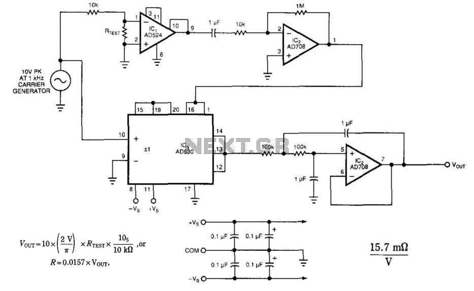
The circuit employs a synchronous detection method to measure low-level resistances. Other low-resistance measuring circuits may introduce excessively large currents into the system under test. This circuit synchronously demodulates the voltage drop across the system under test, allowing the...
A pulse width modulator (PWM) is a device that may be used as an efficient light dimmer or DC motor speed controller. The circuit described here is for a general purpose device that can control DC devices which draw...
The circuit was originally available in kit form from a surplus supplier, but it is likely more widely accessible now. It introduces innovative concepts such as utilizing a 555 timer as a pulse width modulator (PWM) and employing serial/parallel...
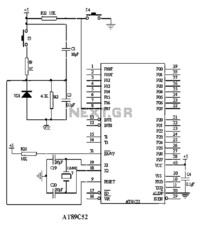
The American Atmel AT89C52 is a low-voltage, high-performance CMOS 8-bit microcontroller chip that contains 8KB of rewritable program memory and 256B of random access data memory (RAM). Atmel's high-density devices utilize non-volatile memory technology and are compatible with the...
Warning: include(partials/cookie-banner.php): Failed to open stream: Permission denied in /var/www/html/nextgr/view-circuit.php on line 713
Warning: include(): Failed opening 'partials/cookie-banner.php' for inclusion (include_path='.:/usr/share/php') in /var/www/html/nextgr/view-circuit.php on line 713