
Transformerless Power Supply
This power supply circuit is particularly notable for its use of capacitive reactance, which allows for a compact design that minimizes heat generation. The circuit's ability to provide a stable 12V output while maintaining a low current draw makes it suitable for powering low-power logic circuits. The inclusion of optical isolators enhances safety by providing electrical isolation between the control circuit and the mains voltage, effectively reducing the risk of electric shock.
The use of a suppressor type capacitor (C1) directly across the mains supply is critical for filtering out high-frequency noise, ensuring stable operation of the power supply. The zener diodes (ZD1, ZD2) serve to regulate the output voltage and protect the circuit from voltage spikes, while the bridge rectifier converts the AC voltage to DC, making it suitable for powering electronic components.
For applications requiring higher current capacity, careful selection of components is necessary to ensure they can handle the increased load without overheating or failing. This project emphasizes the importance of safety precautions, such as the use of fuses, and the necessity for a thorough understanding of electrical principles before attempting to construct the circuit. The design's flexibility allows for modifications, such as adjusting the output voltage by changing the zener diode values, which can cater to a variety of low-power applications.
In summary, this power supply project represents a unique approach to providing low-voltage power without the need for a transformer, making it an economical solution for specific electronic applications, while also highlighting the inherent risks involved in working with mains voltage.A power supply project without using a power supply. This can save the expense of buying a transformer, but presents potentially lethal voltages at the output terminals. Under no circumstances should a beginner attempt to build such a project. Electric Shock Hazard. In the UK, the neutral wire is connected to earth at the power station. If you touch the "Live" wire, then depending on how well earthed you are, you form a conductive path between Live and Neutral. DO NOT TOUCH the output of this power supply. Whilst the output of this circuit sits innocently at 12V with respect to (wrt) the other terminal, it is also 12V above earth potential. Should a component fail then either terminal will become a potential shock hazard. If you are not experienced in dealing with it, then leave this project alone. Although Mains equipment can itself consume a lot of current, the circuits we build to control it, usually only require a few milliamps.
Yet the low voltage power supply is frequently the largest part of the construction and a sizeable portion of the cost. This circuit will supply up to about 20ma at 12 volts. It uses capacitive reactance instead of resistance; and it doesn`t generate very much heat. The circuit draws about 30ma AC. Always use a fuse and/or a fusible resistor to be on the safe side. The values given are only a guide. There should be more than enough power available for timers, light operated switches, temperature controllers etc, provided that you use an optical isolator as your circuit`s output device.
(E. g. MOC 3010/3020) If a relay is unavoidable, use one with a mains voltage coil and switch the coil using the optical isolator. C1 should be of the `suppressor type`; made to be connected directly across the incoming Mains Supply.
They are generally covered with the logos of several different Safety Standards Authorities. If you need more current, use a larger value capacitor; or put two in parallel; but be careful of what you are doing to the Watts. The low voltage `AC` is supplied by ZD1 and ZD2. The bridge rectifier can be any of the small `Round`, `In-line`, or `DIL` types; or you could use four separate diodes.
If you want to, you can replace R2 and ZD3 with a 78 Series regulator. The full sized ones will work; but if space is tight, there are some small 100ma versions available in TO 92 type cases. They look like a BC 547. It is also worth noting that many small circuits will work with an unregulated supply. You can, of course, alter any or all of the Zenner diodes in order to produce a different output voltage.
As for the mains voltage, the suggestion regarding the 110v version is just that, a suggestion. I haven`t built it, so be prepared to experiment a little. I get a lot of emails asking if this power supply can be modified to provide currents of anything up to 50 amps. It cannot. The circuit was designed to provide a cheap compact power supply for Cmos logic circuits that require only a few milliamps.
The logic circuits were then used to control mains equipment (fans, lights, heaters etc. ) through an optically isolated triac. If more than 20mA is required it is possible to increase C1 to 0. 68uF or 1uF and thus obtain a current of up to about 40mA. But `suppressor type` capacitors are relatively big and more expensive than regular capacitors; and increasing the current means that higher wattage resistors and zener diodes are required. If you try to produce more than about 40mA the circuit will no longer be cheap and compact, and it simply makes more sense to use a transformer.
🔗 External reference
Related Circuits
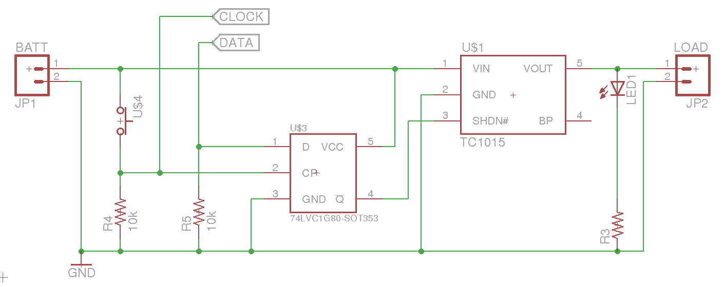
A soft power switch for a microcontroller is designed such that a momentary switch can activate the circuit, including the microcontroller. When the switch is pressed a second time, the microcontroller is capable of shutting itself down after executing...
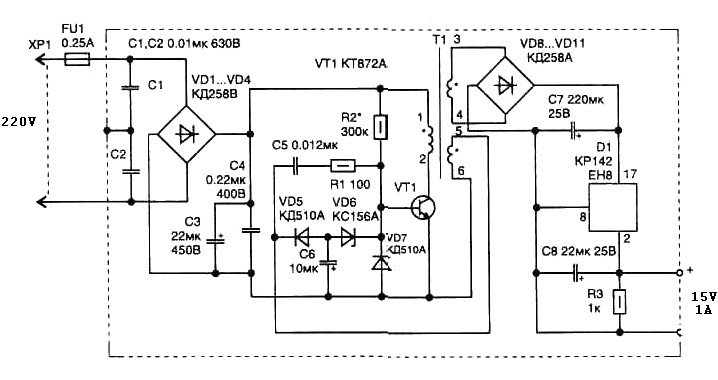
The pulse transformer T1 utilizes a ferrite core, specifically M2500NMS-2 or M2000NM9, with dimensions of Sh5h5 (cross-section of the magnetic coils at 5G—5 mm with a center gap). The winding wire is of type PEL-2. The primary winding consists...
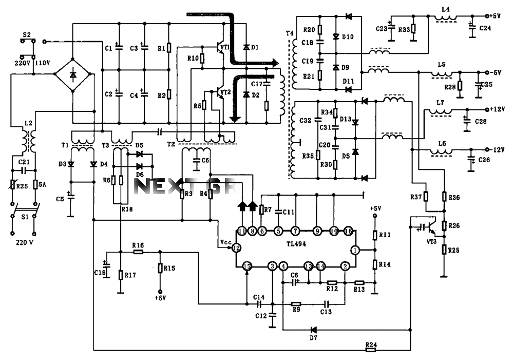
The BE-150 mainframe computer features a switching power supply circuit. The circuit utilizes the oscillation control IC TIA94. A 22V voltage is supplied through the power switch S1, fuse, filter capacitor C21, L2, and a mutual inductance filter, which...
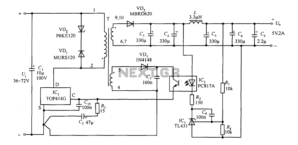
The circuit consists of a 5V TOP414G isolated switching power supply with a 2A output. C1 serves as the input filter capacitor. The circuit includes a voltage clamp protection mechanism composed of VD1. The control terminal is connected to...
High-energy capacitors can produce hundreds of amps when short-circuited, potentially causing severe burns, fires, and property damage. It is essential to be aware of these hazards when using such capacitors and to take precautions to avoid accidental short-circuits. The...
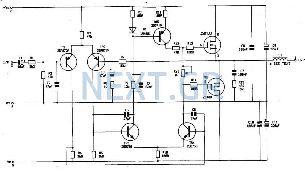
In my opinion that is the best buildable high power amplifier out there. Quality of sound is just remarkable. This is a real bomb proof amplifier like the best Valve amps. Power supply circuit is also shown. Now lets...
Warning: include(partials/cookie-banner.php): Failed to open stream: Permission denied in /var/www/html/nextgr/view-circuit.php on line 713
Warning: include(): Failed opening 'partials/cookie-banner.php' for inclusion (include_path='.:/usr/share/php') in /var/www/html/nextgr/view-circuit.php on line 713