
Controller keeps circuits cool
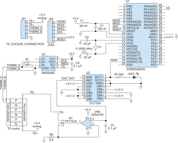
The cooling system described integrates several key components to achieve effective temperature regulation for sensitive electronic devices. The ATmega8535 microcontroller serves as the central processing unit, executing control algorithms to maintain optimal operating conditions. The PWM signal generated by the microcontroller is critical for modulating the cooling device's power, allowing for fine-tuned adjustments based on real-time temperature feedback.
The thermistor-to-digital converter plays a vital role in translating analog temperature readings into a digital format that the microcontroller can interpret. Utilizing a three-wire SPI interface facilitates efficient communication between the converter and the microcontroller, ensuring timely updates on temperature changes.
The TLC7524 DAC is responsible for converting the PWM signal into a corresponding analog voltage, which is essential for controlling the cooling device's operational state. The operational amplifier amplifies this control voltage, providing the necessary signal strength to drive the MOSFET (Q1). This MOSFET acts as a switch, allowing for the delivery of up to 2 A of current to the cooling system, thus enabling effective thermal management.
Timer1 and Timer2 are integral to the system's functionality. Timer1 is programmed to execute the temperature measurement routine, averaging multiple readings to provide a stable temperature value that mitigates the effects of transient fluctuations. Timer2 continuously monitors the average temperature against a predefined setpoint, dynamically adjusting the PWM output to regulate the cooling power applied to the device.
Overall, this cooling system design exemplifies an effective approach to enhancing the performance and longevity of sensitive electronic instruments through precise temperature control. The integration of microcontroller-based feedback mechanisms and efficient power management components ensures a reliable operation, crucial for applications involving infrared detection and other temperature-sensitive technologies.Cooling an instrument or a device can improve the SNR (signal-to-noise ratio), and it can also prolong product life. For example, the dark-and-noise signal of an infrared detector`s output at room temperature can be an order of magnitude smaller when cooled.
We used the cooling device we built as part of a study of semiconductors. Figure 1 shows the block diagram of the system; Figure 2 ( view Figure 2 ) shows the circuit schematic. The design uses the temperature feedback signal to optimize the system. The heart of the design is an ATmega8535 microcontroller. It produces a PWM (pulse-width modulation) signal based on a temperature measurement. A thermistor-to-digital converter produces a digital output on its three-wire SPI (serial peripheral interface), sending the data to the microcontroller. A TLC7524 DAC (digital-to-analog converter) generates a control voltage from the PWM signal. The voltage controls the cooling device through an op amp and MOSFET (Q1), which can produce up to 2 A of control current.
The Timer1 code reads the temperature data and computes an average value from 50 measurements. The Timer2 code compares the measured temperature to the temperature setting and adjusts the current to the cooling controller through the microcontroller`s PWM output signal. 🔗 External reference
Related Circuits
Foggers used to generate fog and smoke effects operate by heating a special fogger fluid. They consist of a heating element that is maintained at the correct temperature using a thermostat. When the operator wants to generate smoke, they...
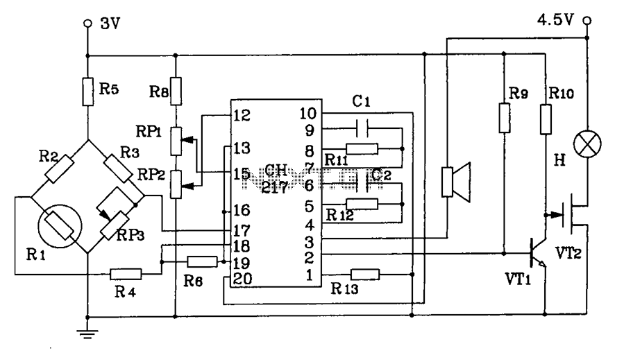
CH217 is a monolithic gas detection alarm integrated circuit. The gas detection alarm circuit diagram includes R1 as the gas sensing probe, where the resistance increases as the gas concentration decreases linearly. RP3 is used to adjust the output...
This is a circuit to use a standard, low quality opto isolator to transfer an analogue signal with reasonable linearity and without complicated feedback loops to monitor and linearise it. The circuit was designed to interface a mains driven...
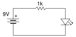
Beginner's Tutorial 1: Building a Circuit on Breadboard - how to build a simple and easy circuit on a breadboard for beginners in electronics. Learn to use an LED and a resistor. This tutorial serves as an introductory guide for...
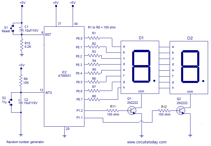
A simple random number generator utilizing the 8051 microcontroller. The AT89S51 is the controller employed in this setup. The circuit design for the random number generator based on the AT89S51 microcontroller involves several essential components and connections. The AT89S51 microcontroller,...
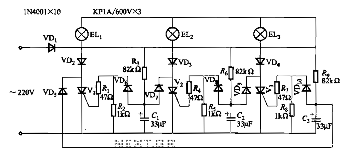
The circuit operates with a 220V mains supply through a diode (VDi) configured as a half-wave rectifier. Capacitors C1 to C3 are charged, and due to the lack of full synchronization in the charging process, a pilot thyristor is...