
Electronic watchdog circuit
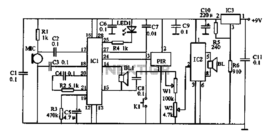
The described circuit employs a Doppler effect sensor (N1) to detect motion within a specified area. The RD627 sensor is sensitive to changes in frequency caused by motion, allowing it to detect the presence of individuals or objects. When no motion is detected, the output remains low, ensuring that the operational amplifier (N2) remains inactive. The LM358 is configured to amplify the low-frequency signal generated by N1 when movement is detected.
The output from N2 drives a transistor (VT), which acts as a switch. In the absence of a signal, the transistor remains off, preventing current flow to the barking imitation circuit (N3). However, once the Doppler sensor detects motion, it produces a low-frequency signal that is amplified by N2. The amplified signal turns on the transistor, allowing current to flow to the KD5608 integrated circuit, which generates a barking sound to deter potential intruders.
The circuit's effectiveness can be fine-tuned by adjusting the potentiometer (RP) connected to the sensor. This adjustment alters the sensitivity of the Doppler sensor, allowing the user to set the desired monitoring distance according to the specific application requirements. The entire arrangement is designed to provide a reliable and efficient solution for security monitoring, utilizing sound as a deterrent for unauthorized entry into a designated area.Doppler effect sensor Nl (RD627), operational amplifier N2 (LM358), the sound of dogs barking imitation special integrated circuit N3 (KD5608) and other components. When nobody in Nl Monitoring area of activity, Nl of feet without signal output, O pin output N2 is low potential, VT cutoff, N3 feet of low potential instead of working. When Nl Monitoring area was activity, which pin outputs a low frequency signal, the signal amplification by N2 after making VT conduction, thus, N3s feet to get a positive trigger signal issued barking.
This activity in the region to promote sound Nl Lin as the man to leave the area, and the master alarm. Adjust RP. Nl can change the Monitor distance.
Related Circuits
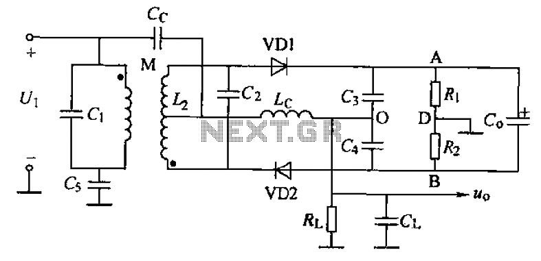
A common phase frequency detector can be categorized into mutual coupling and capacitive coupling frequency discriminators based on their coupling methods. The improved mutual coupling ratio discriminator circuit is illustrated in the figure, utilizing a 2AP9 diode. The phase...
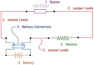
The drive circuit is a basic drive recently designed to accommodate a 27mm passive piezoelectric buzzer, aiming for a sound output exceeding 100dB while minimizing power consumption. Due to constraints related to product cost and structural size, the circuit...
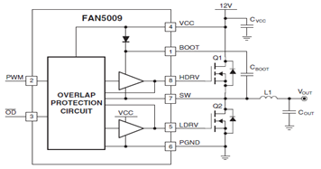
The schematic illustrates a typical application circuit for the FAN5009, a dual bootstrapped 12V high-frequency MOSFET driver. When integrated with a multi-phase PWM controller and power MOSFETs, it can form a complete core voltage regulator for microprocessors, as specified...
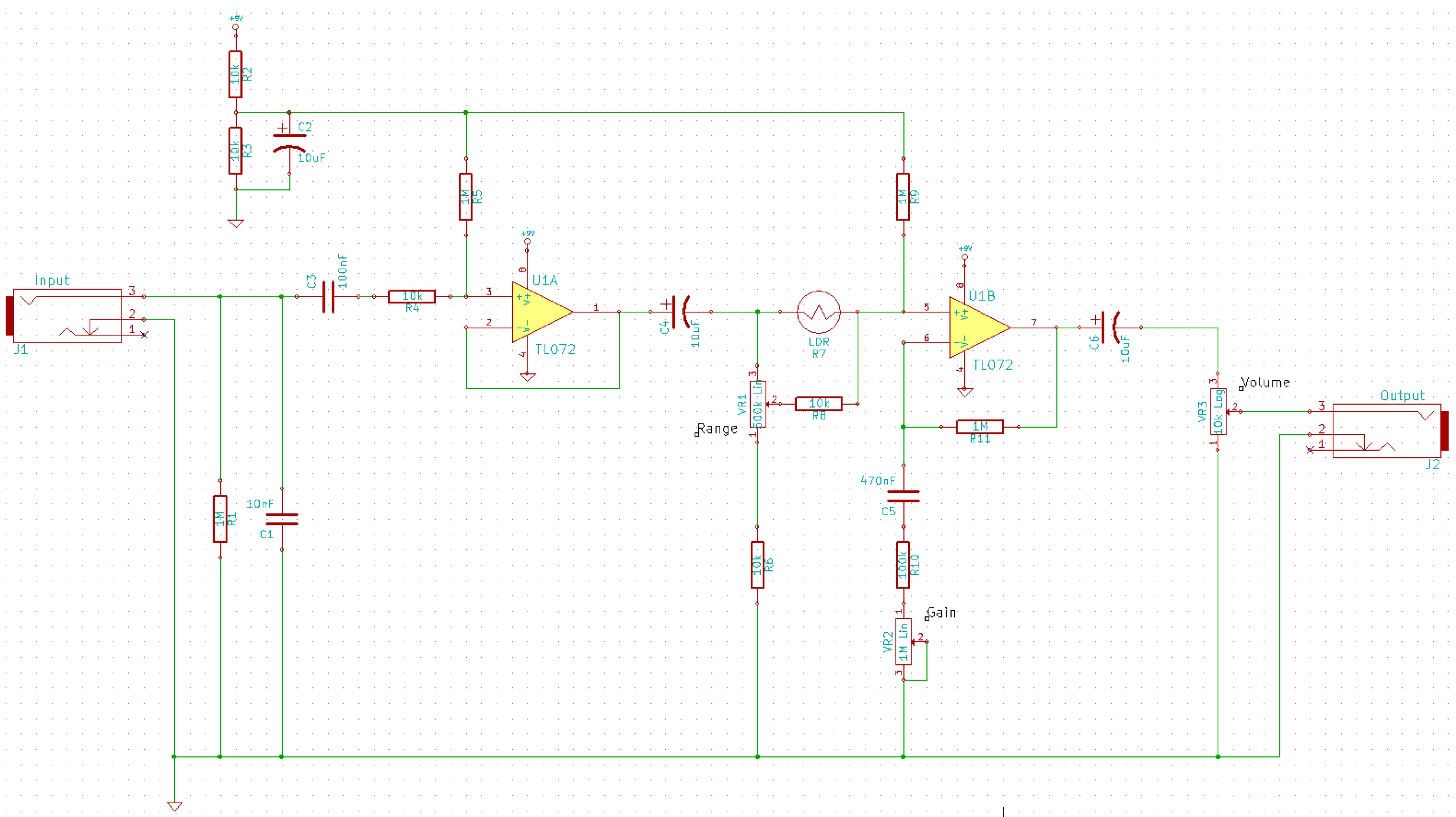
This is a simplified schematic for the Solar Lifeforce. The design eliminates the expression/CV output features and the toggle for the buffer, making it a straightforward circuit. It may benefit from adding small capacitors between R5 and ground, as...
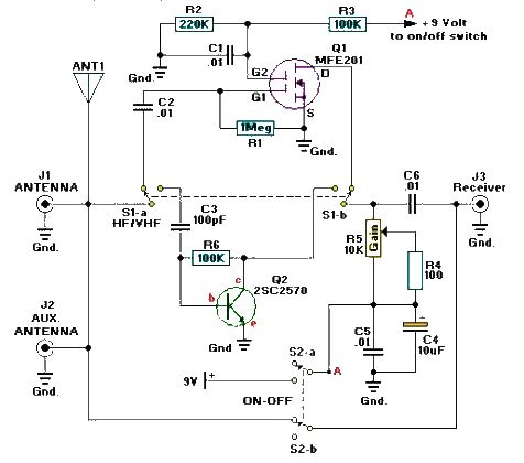
A simple and efficient active antenna electronic project can be designed using this electronic schematic circuit based on transistors. This active antenna project is effective for a wide range of RF frequencies, covering three RF bands: HF, VHF, and...
Mechanical contacts have the disadvantage of wearing out. Therefore, it is practical to use an electronic touch switch in certain situations. This type of touch switch utilizes the resistance of human skin for its switching action. The schematic illustrates...
Warning: include(partials/cookie-banner.php): Failed to open stream: Permission denied in /var/www/html/nextgr/view-circuit.php on line 713
Warning: include(): Failed opening 'partials/cookie-banner.php' for inclusion (include_path='.:/usr/share/php') in /var/www/html/nextgr/view-circuit.php on line 713