
automatic light
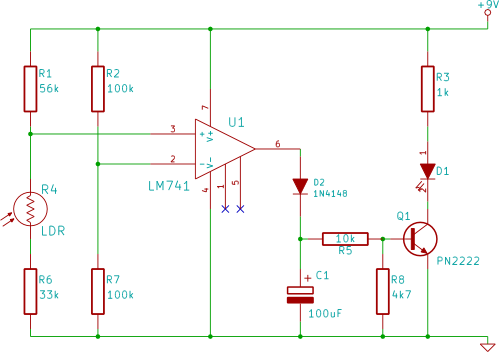
This circuit utilizes a light-dependent resistor (LDR) as the primary sensor to detect ambient light levels. The LDR is a type of resistor whose resistance decreases with increasing incident light intensity. When the light level drops below a predefined threshold, the resistance of the LDR increases, triggering a change in voltage across the circuit.
The circuit typically includes a power supply, such as a battery, connected to a voltage divider formed by the LDR and a fixed resistor. The output from this voltage divider is fed into a comparator or a transistor configured as a switch. When the voltage across the LDR exceeds a certain level, it turns on the transistor, allowing current to flow through the LED, which illuminates.
To enhance the circuit's functionality, a potentiometer may be included in the design, allowing users to adjust the sensitivity of the LDR and set the light threshold at which the LED activates. This feature provides flexibility, enabling users to customize the circuit for various lighting conditions.
Additional components such as a capacitor can be added to smooth out any fluctuations in the light level, preventing the LED from flickering as the light changes. A resistor in series with the LED limits the current to protect it from excessive current that could cause damage.
This simple yet effective circuit serves as an excellent introduction to basic electronics concepts, including light sensing, voltage dividers, and transistor switching, while providing a practical application in ambient light detection.In this electronic breadboard circuit for beginners in electronics, when the ambient light level drops below a certain level, the LED switches on automatically.. 🔗 External reference
Related Circuits

When connecting this element in a voltage divider configuration, a high and low signal can be generated based on the amount of light detected by the sensor. An NPN transistor configured as an inverter further filters this signal to...
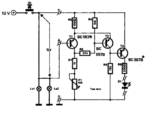
This simple circuit using a single transistor turns ON the relay when light falls on the LDR. The potentiometer is adjusted for the required sensitivity. The power supply is 6V. Be careful about the impedance of the relay. Its...
The circuit described below monitors the car's brake lights and indicates their operational status using a light-emitting diode (LED). This functionality helps prevent fines for driving with defective brake lights and enhances road safety. The monitor relies on the...

The following circuit illustrates an Automatic Loudness Control Circuit Schematic. This circuit is based on the TL072 integrated circuit. Features include various functionalities. The Automatic Loudness Control Circuit is designed to adjust audio signal levels dynamically, enhancing the listening experience...
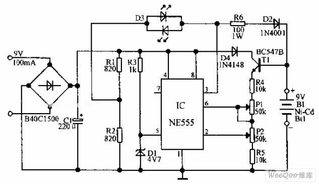
An automatic Ni-Cd battery charger circuit is depicted in the provided image. The internal comparator of the NE555 timer is configured to a reference voltage of 4.7V using a Zener diode. When the voltage at pin 6 exceeds this...
The following circuit illustrates the use of the AD8531 integrated circuit for the automatic control of LCD panel backlighting. Features include the ability to compensate for aging effects. The AD8531 is a precision operational amplifier that is well-suited for applications...
Warning: include(partials/cookie-banner.php): Failed to open stream: Permission denied in /var/www/html/nextgr/view-circuit.php on line 713
Warning: include(): Failed opening 'partials/cookie-banner.php' for inclusion (include_path='.:/usr/share/php') in /var/www/html/nextgr/view-circuit.php on line 713