
Light Barrier Detector
This circuit employs a light-dependent resistor (LDR) in conjunction with a single transistor to control a relay, enabling it to operate based on ambient light conditions. The LDR, which exhibits a low resistance in the presence of light, is the key component that influences the transistor's state. When light falls on the LDR, its resistance decreases significantly, allowing current to flow through the base of the transistor. This action saturates the transistor, effectively turning it ON and energizing the relay coil, which in turn closes the relay contacts to power an external load.
The circuit is powered by a 6V supply, which is suitable for both the transistor and the relay operation. It is crucial to select a relay with an impedance of at least 60 ohms to ensure that the circuit functions correctly without drawing excessive current that could damage the transistor or the power supply.
A potentiometer is included in the circuit to adjust the sensitivity of the light detection. By varying the resistance of the potentiometer, the threshold at which the LDR activates the transistor can be fine-tuned. This allows for flexibility in different lighting conditions, enabling the circuit to respond appropriately to changes in ambient light.
When light is obstructed, the resistance of the LDR increases dramatically, which leads to a reduced current flow to the base of the transistor. As a result, the transistor enters a cutoff state, effectively turning OFF the relay and opening the circuit to the load. This simple yet effective design is commonly used in applications such as automatic lighting systems, alarm systems, and other devices that require light-sensitive control.This simple circuit using a single transistor turns ON the relay when light falls on the LDR. The potentiometer is adjusted for the required sensitivity. The power supply is 6V. Be careful about the impedance of the relay. Its impedance should not be less that 60ohm. Its working can be explained as follows: With the light falling on the LDR,its resistance is low and the transistor is saturated and turns the relay ON. When light is obstructed, the LDRs resistance becomes very high. The potentiometer shorts the transistors base to ground and it is cut off. Hence the relay is OFF. 🔗 External reference
Related Circuits
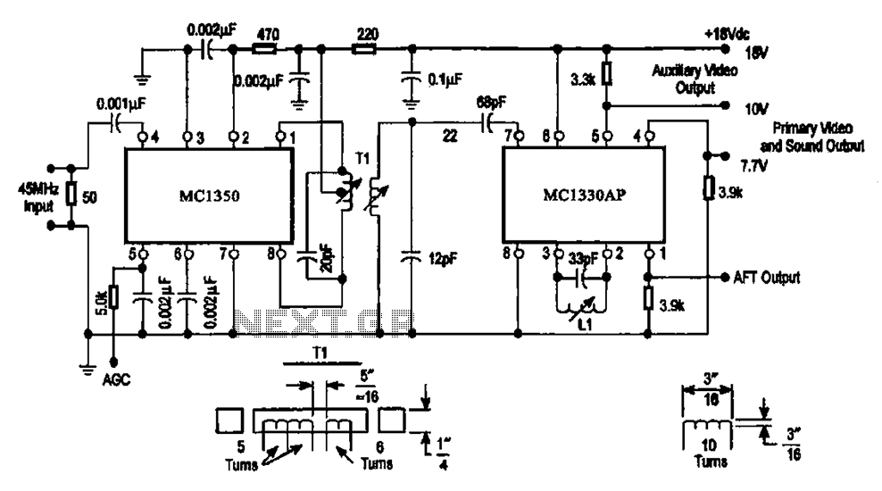
The circuit features an IF processing section utilizing the MC1350 and a video detector, the MC1330AP, which are integrated to form a combined video processing system. The modulation of the circuit is dependent on the image signal, with the...
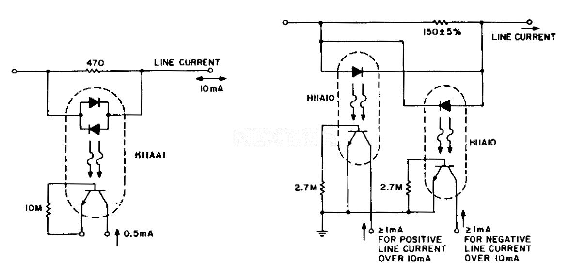
The detection of line-current flow and its indication at an electrically remote point is essential for line status monitoring in various telephone systems and auxiliary systems. The monitoring circuit must minimally unbalance or load the line, while also being...
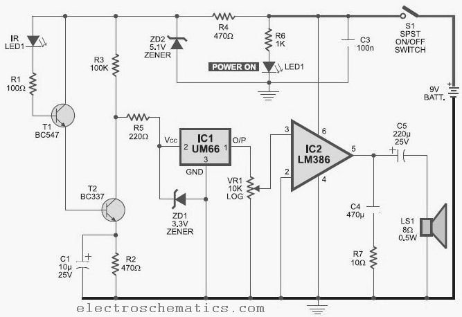
This infrared detector is capable of detecting the presence of modulated infrared signals in its vicinity from various electronic sources, such as an IR handheld remote. The infrared detector operates by utilizing a photodetector that is sensitive to infrared light....
The success or failure of lighting upgrades depends on the quality of components and workmanship. Proper wire routing is essential to prevent insulation chafing. The quality of soldering connections is crucial, as poor solder joints can corrode and fail....
Constantly changing light and sound analog controller circuit 01 The described circuit functions as an analog controller designed to modulate light and sound outputs in a dynamic manner. This circuit typically integrates various electronic components, including resistors, capacitors, transistors, and...
A simple test circuit designed for troubleshooting audio and radio equipment. It can inject a square wave signal rich in harmonics or be used with headphones as an audio tracer. A single-pole double-throw switch is utilized to toggle between...
Warning: include(partials/cookie-banner.php): Failed to open stream: Permission denied in /var/www/html/nextgr/view-circuit.php on line 713
Warning: include(): Failed opening 'partials/cookie-banner.php' for inclusion (include_path='.:/usr/share/php') in /var/www/html/nextgr/view-circuit.php on line 713