
Automatic light control one lamp lighting circuit b
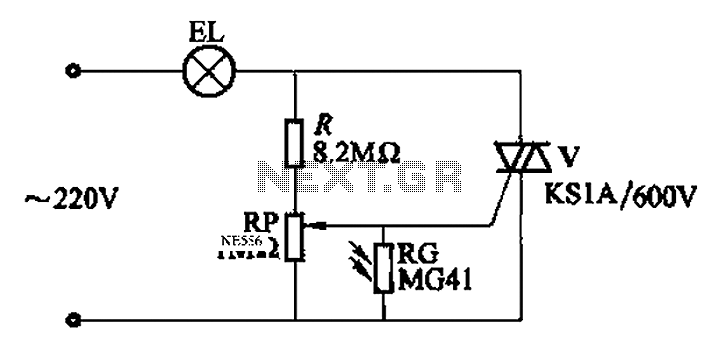
The automatic light control circuit utilizes a photoresistor (light-dependent resistor) to detect ambient light levels. When the light intensity falls below a certain threshold, the photoresistor's resistance increases, triggering the thyristor to conduct and illuminate the lamp. Conversely, during daylight, the resistance of the photoresistor decreases, causing the thyristor to turn off and extinguish the lamp.
In the first configuration (Figure 2-86 (a)), the capacitor C plays a crucial role in stabilizing the circuit's operation. If the circuit experiences flickering, increasing the capacitance can help smooth out the voltage fluctuations, providing a more stable operation. This adjustment is essential for ensuring reliable performance, particularly in environments with varying light conditions.
The second configuration (Figure 2-86 (b)) incorporates a potentiometer RP, allowing users to fine-tune the brightness of the lamp. This feature is beneficial in applications where different illumination levels are desired, such as in night lights, where a softer glow may be preferable. The ability to adjust brightness enhances the versatility of the circuit, making it suitable for various lighting applications.
Overall, this automatic light control circuit is a practical solution for energy-efficient lighting, providing convenience and adaptability based on the surrounding light conditions. The simplicity of the design, combined with the functionality of the components used, makes it an effective choice for automatic lighting systems. Automatic light control circuit lights automatically illuminate the lamp when dark, lights automatically turn off when daybreak. (1) One of the automatic light control circuit lighting circuit 286 shown in FIG. Both circuits are bidirectional thyristor tube, the circuit is simple. For Figure 2-86 (a). If the photoresistor RG no light when light is off, the capacitor C should be increased capacity. Inadequacies of the circuit in the sense that before each automatic lights on or off flicker. For Figure 2-86 (b), adjustment potentiometer RP, can change the brightness of the light. The circuit can be used as night light use.
Related Circuits

This design circuit functions as a sine wave oscillator, providing both sine and square wave outputs across a frequency range from below 20 Hz to above 20 KHz. The oscillation frequency can be easily adjusted by varying a single...
If an application utilizes a MOSFET to switch a load, it is straightforward to incorporate short-circuit or overload protection. This can be achieved by leveraging the internal resistance RDS(ON), which generates a voltage drop proportional to the current flowing...
The circuit depicted is designed to protect a system from power supplies that may exceed safe limits. An example of this is small consumer products that utilize external AC adapters, where there is a risk of accidentally connecting the...
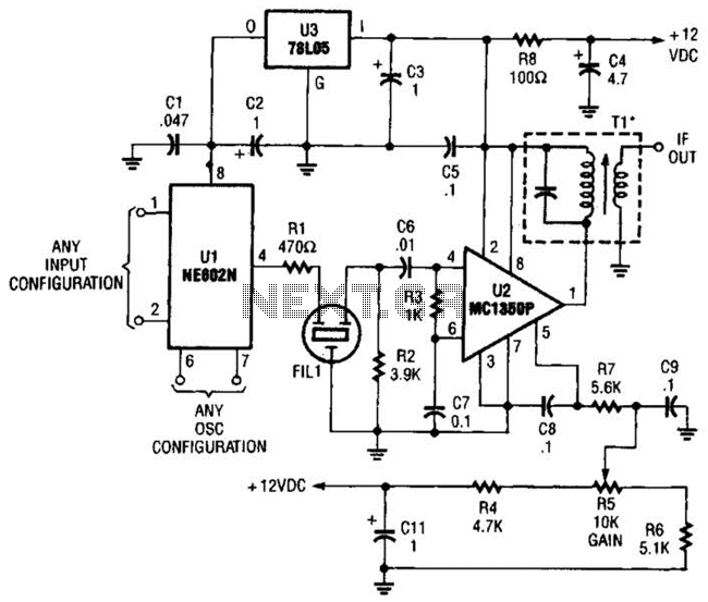
By using an NE602 with a filter and an MC1350P IC, a front end and an IF system for a basic superheterodyne receiver can be built with few parts. Tl is any suitable IF transformer for 262 kHz, 455...
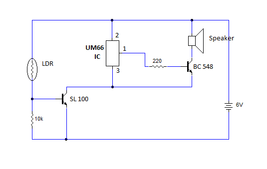
This article provides instructions for creating a light-sensitive morning alarm circuit. The circuit utilizes an LDR (Light Dependent Resistor) or photoresistor to detect morning light, which triggers the alarm section. When light is detected, the circuit produces a melodious...
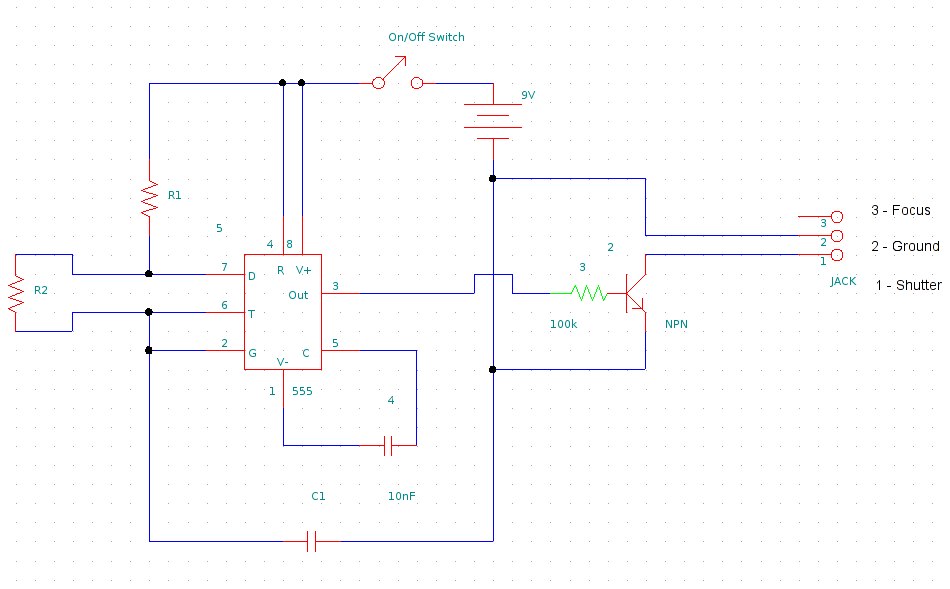
This document provides information on constructing a DIY time-lapse circuit that enables a camera to automatically capture images at specified time intervals. These images can then be compiled to create a time-lapse film. The circuit utilizes a 2.5 mm...