
Simple Morning Alarm Circuit Using LDR and UM66

The light-sensitive morning alarm circuit is designed to provide an effective and user-friendly solution for waking up to natural light. The core component, the LDR, is strategically placed to maximize exposure to sunlight, ensuring reliable operation. The circuit's design is straightforward, facilitating easy assembly for individuals with basic electronic skills.
The LDR operates by varying its resistance based on ambient light levels. In darkness, the resistance is high, preventing current flow and keeping the transistor in an off state. As light levels increase, the resistance of the LDR drops, allowing current to flow through the circuit. This action turns on the NPN transistor (SL 100), which acts as a switch to activate the alarm section.
The alarm section is comprised of the UM66 melody generator IC, which is designed to produce musical tones. The output from the UM66 is typically a low-level audio signal that requires amplification to drive a speaker effectively. The BC 548 NPN transistor serves this purpose by amplifying the signal from the UM66 before it reaches the speaker. This amplification is crucial for ensuring that the alarm tone is audible enough to wake the user.
The circuit's power requirements are minimal, with a single 6V battery providing sufficient energy for operation. This low power consumption is advantageous, allowing the circuit to function for extended periods without the need for frequent battery replacements. Overall, this light-sensitive morning alarm circuit is an economical and practical solution for individuals seeking a gentle wake-up experience, leveraging the natural light of the morning to trigger an audible alarm.This article helps you to make a Light Sensitive Morning Alarm circuit. The morning light is sensed by an LDR (Light Dependent Resistor) or Photoresistor and it triggers the alarming section. The circuit generates a melodious tone when light falls on it. Wire-up the circuit as shown in schematic diagram and place the LDR next to the window pane cl oser to your bed. The LDR is more sensitive to light, so make sure it will not be false triggered. All the electronic components used in this circuit is cheap, so you can make this at your own home at very low cost and it consumes very less power, hence it ensures long working life. The light sensing part consists of a Light Dependent Resistor (LDR) or a photoresistor, which is a two terminal device having the capability to detect light (Photons).
The LDR decreases its resistance when suitable amount of light falls on it. The working principle of this circuit is based on the switching action of an npn transitor (SL 100). As i mentioned above, the LDR conducts current (Lowers its resistivity), when light falls on it and make the transistor switched ON. The alarming section of the circuit consists of a Melody Generator IC (UM66), an NPN transistor (BC 548) and a Speaker.
The output voltage from the Light Sensor Section is used to drive the alarm. The tone generated by UM66 is fed to the base of an NPN transistor, inorder to amplify the signal enough to drive the Loud-Speaker. The whole circuit is powered by a Single 6V battery. 🔗 External reference
Related Circuits
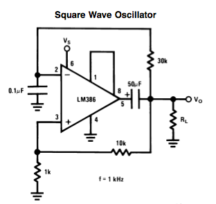
Here is a small LM386-based square-wave oscillator constructed from the following schematic. A 50k potentiometer was used in place of a 30k resistor, which functions as a pitch controller. The audio provided consists of track recordings made in Ableton...
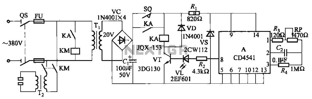
One Foot Spot Welder circuit. The circuit utilizes the IC CD4541 to provide precise delay characteristics, enabling the electrical time constant necessary for effective welding. This ensures consistent welding quality across identical weldments. For varying weldments, the electrical locator...

This circuit is a 6-band graphic equalizer that allows for the adjustment of low, medium, and high frequencies using the operational amplifier circuit 741. It enables control and mixing of frequencies and tones according to user preferences. The audible...

This circuit is a motion detection sensor that utilizes a light source and a detector in the form of an infrared motion detector. The motion sensor employs an infrared LED and a phototransistor. The sensitivity of the sensor can...

The touch delay switch, as illustrated in the figure, is composed of a CMOS NAND gate and is capable of providing a delay of approximately 10 seconds. It is commonly utilized for the automatic control of lighting in street...

A band-pass filter permits only signals within a specified frequency range to pass through, while attenuating or suppressing those outside this range. This is characterized by a lower frequency limit and an upper frequency limit. A typical implementation is...