
Controlling DC Motors Robotics Tutorial
The interface between DC motors and microcontrollers is critical in many applications, including robotics and automation systems. The Robocore board serves as a versatile platform that simplifies the control of multiple motors while providing essential debugging features through its LED indicators. The use of transistors as electronic switches allows for efficient control of motor operations without the need for high-current signals from the microcontroller. Each transistor pair is strategically selected based on the required current and voltage ratings of the motors, ensuring reliable performance.
The flyback diodes are an essential component of the circuit, as they protect the transistors from voltage spikes caused by the inductive loads of the motors. When a motor is de-energized or its direction is reversed, the collapsing magnetic field generates a back EMF that can exceed the rated voltage of the transistors. Properly rated flyback diodes provide a safe path for this reverse current, effectively shunting it away from the transistors and preventing damage.
When designing the circuit, careful consideration must be given to the power supply requirements. The voltage rating should match the specifications of the motors to ensure optimal performance. Additionally, when employing separate power supplies for the microcontroller and motors, it is crucial to connect the grounds to maintain a common reference point, preventing erratic behavior or circuit malfunction.
In summary, the integration of DC motors with microcontrollers like the Basic X through the Robocore board presents a robust solution for various applications. The careful selection of components, including transistors and flyback diodes, ensures reliable operation and longevity of the circuit, while proper power supply management is vital for successful implementation.The principles of DC motors are covered in the beginner and intermediate sections of this tutorial. This section will cover the electronics needed to interface them to a Basic X microcontoller or other digital chip. The easiest way of controlling motors is using the Robocore. This board contains the driver electronics to control up to 4 DC motors or 2 stepper motors, and features direction LED`s for easy debugging of circuits. Transistors are electronic switches, they allow you to turn on large voltages (the motor power supply) using a very small current (like the output pin of the Basic X). Each pair of transistors is connected to a pin on the micro controller and control the polarity of the current supplied to the motor.
The actual components required would depend on the size of the motors that you want to use. The diodes in the circuit are very important and are called fly back diodes. They are there to prevent voltage spikes from the motors from destroying the transistors. When a motor rotates and changes direction the coils of wire inside it act as a generator and produce a current. This current is called the back electro motive force, or back E. M. F. for short. This current travels back through the circuit, in the form of powerful voltage spikes, to the transistor.
Now, because transistors only allow current to flow in one direction the current hits a bottle neck as the transistor tries to stop the reverse current. If this current is particularly large, say when your reversing the direction of the motor, it will simply blow the transistor, giving your new circuit a pretty short life.
The circuit can be powered using whatever voltage is suitable for your motors. If you are using two power supplies, one to power your Basic X and another to power your motors, you must connect the ground of each supply together or your circuit may not work properly. 🔗 External reference
Related Circuits
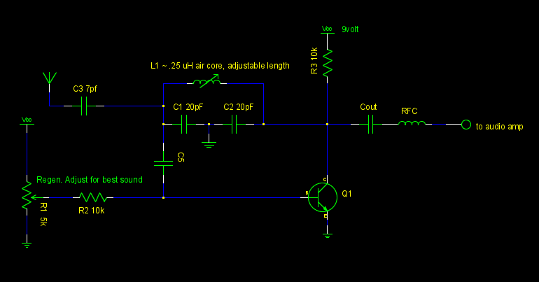
A common emitter Colpitts oscillator was constructed using variable capacitors for C1 and C2, and a few turns of wire wrapped around a pencil for the inductor L. Resistors R1 and R2 were replaced with a trimmer potentiometer to...
The design of this project relies heavily on sensors, which are present in both the control module and the robot. The computer analyzes the signals from these sensors to determine appropriate output actions. The control unit utilizes potentiometers as...
Colpitts Oscillator tutorial and the theory behind the design of the Colpitts Oscillator, which uses an LC oscillator tank circuit to generate sine waves. The Colpitts oscillator is a type of electronic oscillator that utilizes a tank circuit composed of...

A brief history: Like many tutorials, this one begins with a historical overview. However, it must be noted that there is limited background information available regarding the development of 7-segment displays. 7-segment displays are widely used electronic components that...

A relay is an electromechanical switch that operates by opening and closing under the control of another electric circuit. When current flows through the relay's coil, a magnetic field is generated, causing an armature to move, which either establishes...
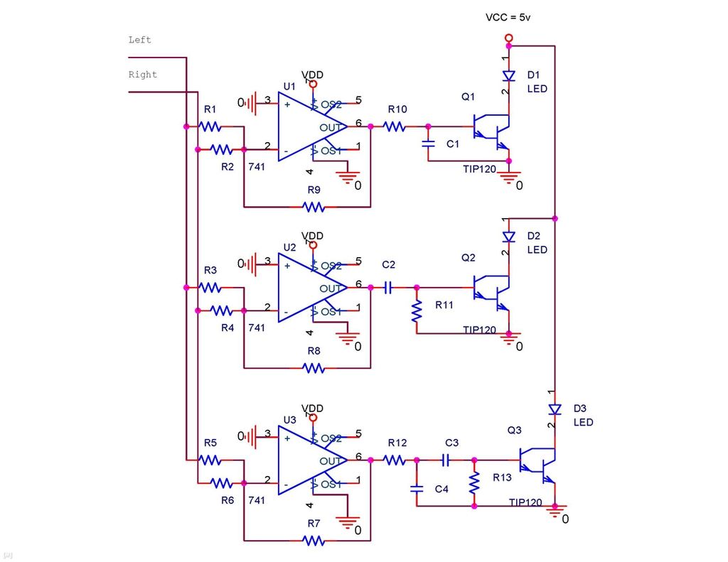
It is possible to synchronize the LEDs so that the speakers continue to play loudly while the LEDs are not always illuminated during music playback. The individual has a solid understanding of electrical concepts and is seeking a method...