
automatic loudness control circuit schematic
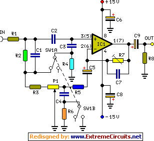
The implementation of tone controls in audio systems is crucial for compensating for the ear's frequency response at different sound pressure levels. The Fletcher-Munson curves, which depict equal-loudness contours, indicate that at lower volumes, the human ear is less sensitive to low and high frequencies compared to mid-range frequencies. This phenomenon necessitates the incorporation of adjustable tone controls that can modify the bass, midrange, and treble levels to enhance the listening experience.
A typical audio circuit may include a preamplifier stage, where the audio signal is first processed. Following this, a tone control circuit can be integrated, often utilizing operational amplifiers (op-amps) configured in a feedback arrangement to create bass and treble boost/cut functionality. The control interface may consist of potentiometers allowing users to adjust the gain of specific frequency bands.
For instance, a low-pass filter can be employed to adjust the bass frequencies, while a high-pass filter can manage treble frequencies. The design may also incorporate a band-pass filter for mid-range adjustments. The output of the tone control circuit feeds into the power amplifier stage, which drives the speakers.
In summary, a well-designed tone control circuit is essential for achieving balanced audio reproduction that caters to the non-linear sensitivity of the human ear, ensuring an enhanced listening experience across various volume levels.In order to obtain a good audio reproduction at different listening levels, a different tone-controls setting should be necessary to suit the well known behavior of the human ear. In fact, the human ear sensitivity varies in a non-linear manner through the entire audible frequency band, as shown by Fletcher-Munson curves..
🔗 External reference
Related Circuits

An RF power amplifier is an electronic amplifier used to convert a low-power radio-frequency signal into a larger signal of significant power, typically for driving the antenna of a transmitter. It is optimized for high efficiency, high output power...
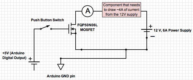
If the ground of the Arduino is disconnected from the negative terminal of the power supply, current flows through the MOSFET, even when the switch is not closed. In an electronic circuit involving an Arduino and a MOSFET, maintaining a...
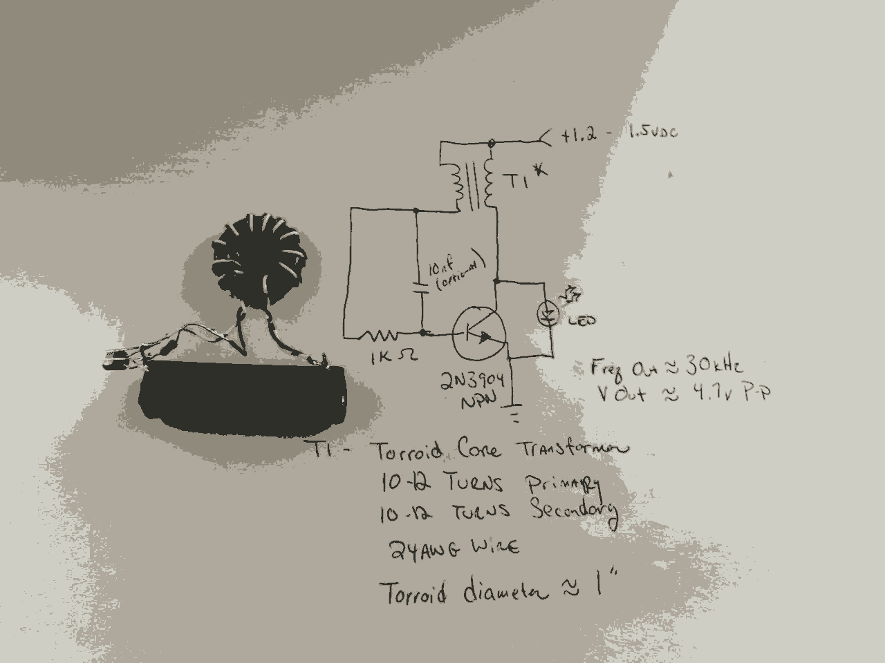
In the previous post, the primary principles of the switching power supply were discussed. Essentially, an oscillator drives a transformer with a ferrite core at a relatively high frequency, thereby minimizing the size, weight, and cost of power supplies....
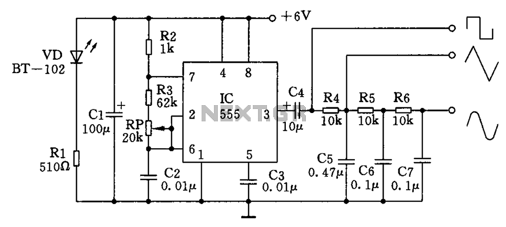
The circuit simultaneously generates a square wave, triangle wave, and sine wave, making it particularly suitable for electronics enthusiasts and students who wish to observe signal waveforms using an oscilloscope. This signal generator circuit is simple, low-cost, and allows...
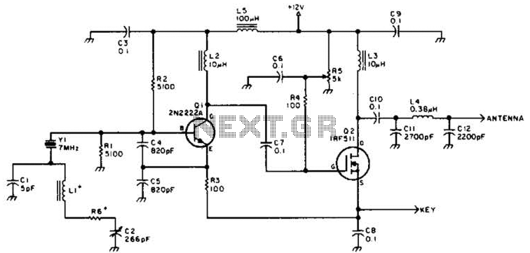
A DSB transmitter is significantly less expensive to construct compared to an SSB transmitter since it does not require filters or phasing networks. This circuit can generate an output of up to 1 watt on the 10-meter band. The...
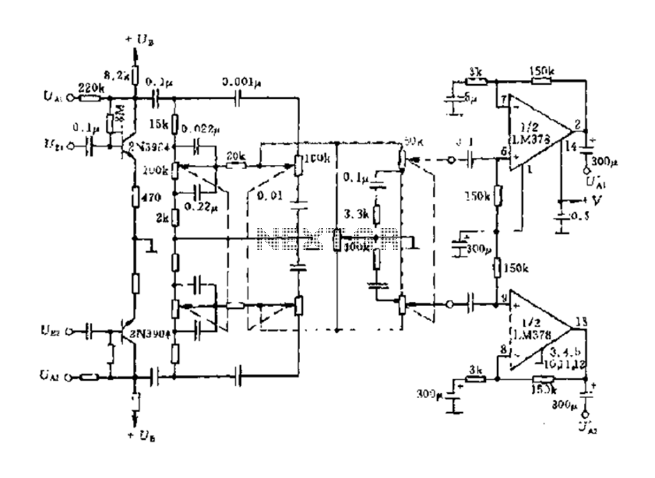
The dual-channel circuit features the LM378 dual operational amplifier and operates with a supply voltage of 24V, supporting an 8-ohm load (or 16 ohms). Each channel delivers an output power of 4W. The circuit includes internal current limiting and...