
Switchless NiCd-NiMH Battery Charger
This circuit serves as an improved solution for current limiting in battery chargers, particularly those designed for low-cost applications. Traditional battery chargers typically employ a single resistor for current limitation, which can lead to inefficiencies and heat generation. The proposed circuit enhances this design by incorporating additional components that optimize performance and reliability.
The schematic may include a combination of transistors, diodes, and operational amplifiers to create a more sophisticated current regulation mechanism. For instance, a transistor can be configured in a feedback loop to monitor the output current. When the current exceeds the preset limit, the feedback mechanism adjusts the base current of the transistor, thereby reducing the voltage drop across the load and maintaining the desired current level.
Additionally, the use of diodes can protect the circuit from reverse polarity and over-voltage conditions, further enhancing the safety and longevity of the charger. Operational amplifiers can be employed to provide precise voltage and current sensing, allowing for more accurate regulation and improved performance under varying load conditions.
Overall, this alternative circuit design not only replaces the traditional current limiting resistor but also provides a more efficient and reliable method for battery charging applications. By offering better thermal management and improved current regulation, it addresses the shortcomings of conventional designs, making it suitable for a wider range of battery types and charging scenarios.This circuit may be used to replace the single current limiting resistor often found in dirt cheap battery chargers. The alternative shown here will event.. 🔗 External reference
Related Circuits
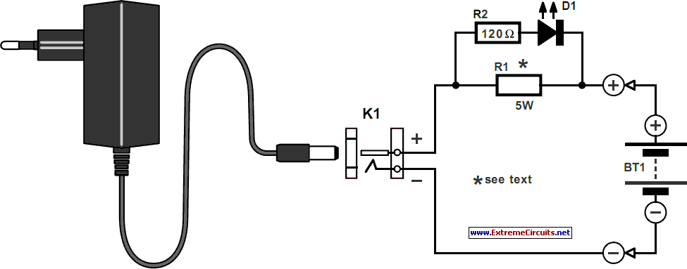
The charger design resembles that of many commercially available chargers. It comprises a mains adapter, two resistors, and a light-emitting diode (LED). This type of charger is effective in practical applications. Resistor R1 has dual functions: it establishes the...

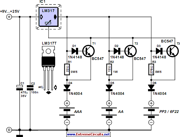
This is a simple and low-cost NiCd and NiMH battery charger. The schematic diagram indicates that the charging current (I) should be set to 1/10 of the battery's rated capacity. For instance, if the battery has a rated capacity...
The first circuit is designed for discharging nickel-cadmium batteries before recharging to eliminate the "memory effect." After discharging, the power is automatically converted to the state of charge. The charging process utilizes pulse-width modulation for constant current, along with...
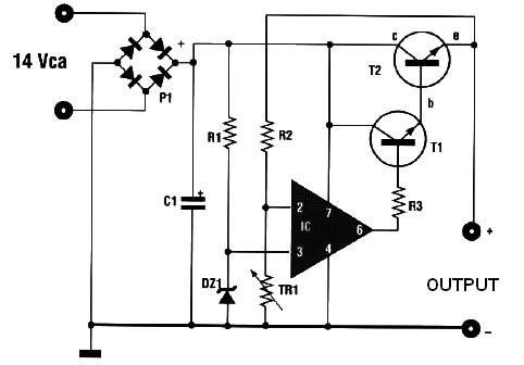
This circuit can automatically and efficiently charge 6V and 12V batteries. A key factor in the successful operation of the circuit is the use of a high-quality transformer [T1] that has excellent insulation and resistance to short circuits. The circuit...
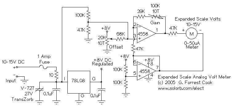
This circuit is used to measure the voltage on a 12V (nominal) lead acid rechargeable battery system. It was specifically designed for use in solar powered systems, but is general enough that it can be used for automotive or...
This automatic battery charger circuit is ideal for charging batteries used in alarm systems that require battery buffering. Caution must be exercised when connecting the battery to ensure correct AC polarity. It is essential to meticulously follow the schematic...
Warning: include(partials/cookie-banner.php): Failed to open stream: Permission denied in /var/www/html/nextgr/view-circuit.php on line 713
Warning: include(): Failed opening 'partials/cookie-banner.php' for inclusion (include_path='.:/usr/share/php') in /var/www/html/nextgr/view-circuit.php on line 713