
Paraphase Tone Controller circuit
The paraphase configuration is an audio processing circuit designed to manipulate frequency response characteristics selectively. Its primary function is to allow for independent adjustments of treble and bass frequencies, which is beneficial in audio applications where specific tonal qualities need enhancement without affecting the overall balance of sound.
The circuit comprises two distinct networks, each consisting of capacitors and resistors that work together to shape the audio signal. The first network, formed by capacitors C1, C2, and C3 in conjunction with resistors R9, R10, and R11, is responsible for one channel of the audio signal, while the second network, comprising capacitors C5, C6, and C7 paired with resistors R12, R13, and R14, handles the other channel.
The configuration allows for the adjustment of either treble or bass by altering the resistance values or capacitance in one of the networks, thereby affecting the frequency response curve. The slope of this curve is determined by the difference in settings of the tone controls, which provides a precise means of tuning the audio output to the listener's preferences.
This design is particularly advantageous in applications where space and component count are critical, as it simplifies the circuit while providing effective control over audio characteristics. Additionally, the paraphase configuration can be integrated into various audio devices, including mixers, amplifiers, and equalizers, enhancing their functionality and user experience.This unique property makes the ˜paraphase configuration of interest if only treble or bass needs to be adjusted - it is not possible to adjust both at the same time! Essentially, it s the difference in setting of the tone controls that determines the slope of the frequency response, and the degree of bass/treble correction.
The circuit is simplicity itself, based on two networks C1-C2-C3/R9-R10-R11 and C5-C6-C7/R12-R13-R14.. 🔗 External reference
Related Circuits
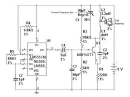
The team is highly interested in the design of a jammer circuit and has begun working on it. However, they are experiencing issues with the circuit, specifically that the signal is not being jammed effectively. The design of a jammer...
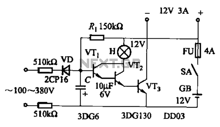
An AC-DC power supply without a power switching circuit is typically utilized for lighting load circuits. Once the power grid is restored, the standby power supply automatically switches on. An automatic switching circuit using a transistor is implemented, with...

The circuit diagram illustrates a simple stepper motor controller utilizing basic components. The driver circuit employs four SL100 transistors to control the motor windings, along with two NOT gates and one XOR gate to decode the two-bit control logic...
The circuit described is a simple intercom system that utilizes a single LM386 integrated circuit, a 2N3904 transistor, and several additional components. The LM386 is a widely recognized amplifier IC commonly employed by electronics enthusiasts in audio applications. In...
The figure illustrates a schematic circuit of a UV sensor. When voltage is applied between the cathode and anode, and UV radiation passes through the quartz glass tube on the cathode's optical surface, the cathode material, which is coated...
Fires can occur for several reasons, such as forgetting to turn off equipment like irons. A fire alarm circuit with a temperature sensor may be one option to secure homes from fire hazards. There are also fire alarm circuits...
Warning: include(partials/cookie-banner.php): Failed to open stream: Permission denied in /var/www/html/nextgr/view-circuit.php on line 713
Warning: include(): Failed opening 'partials/cookie-banner.php' for inclusion (include_path='.:/usr/share/php') in /var/www/html/nextgr/view-circuit.php on line 713