
Automatic Switch For Voltage Converters
The described circuit presents a sophisticated solution for integrating load detection and control into a DC voltage converter application tailored for automotive use. The combination of the LT1070 converter with the load detection circuitry allows for efficient operation while maintaining the necessary voltage levels for the radio. The use of the MBR2545 dual diode ensures that the radio retains memory even when powered off, while the AC128 transistor and associated components facilitate smooth transition between the on and off states of the converter based on load detection. Furthermore, the implementation of Schottky diodes enhances the overall efficiency of the circuit by minimizing voltage drop, which is crucial in automotive applications where space and power conservation are paramount. The design considerations regarding component selection, particularly the PNP germanium transistor and relay specifications, highlight the importance of tailoring the circuit for specific operational requirements, ensuring reliability and performance under varying conditions. This circuit exemplifies modern approaches to DC voltage regulation and control, integrating advanced semiconductor technologies and practical engineering solutions to address common challenges encountered in automotive electronics.New applications for DC voltage converters, such as the workhorse` LT1070, arise every day. These converters can be adapted to nearly every imaginable ratio of input and output voltages. However, all of these circuits and devices have the same shortcoming, which is that they lack an on/off switch. Especially when they are used as a source of 6-V / 12-V power for a car radio, this is highly impractical. The circuit described here adds automatic load detection to the converter. For use in a car, the additional circuitry must be small and fit into a compact enclosure together with the converter. Since the battery voltage and ambient temperature vary over wide ranges, a simple form of load detection must be used.
Besides this, the voltage drop across the load sensing circuitry must naturally be as small as possible. This can be achieved by using ultra-modern` SiGe technology. The 6 V from the battery and the 12 V from the converter are combined in the MB R2545 dual diode. Consequently, a voltage of at least 6 V is always applied to the radio (for memory retention). If the radio is switched on, it draws a current from the 6-V battery, which may be around 100 mA. This current produces a voltage across R1. If this voltage is 75 mV or greater, the AC128 germanium transistor starts conducting and charges electrolytic capacitor C1, which is connected to the gate of the BUZ10.
The MOSFET energises RE1 and thus connects the supply voltage to the converter. As a result, 12-V power is connected to the radio. The resulting increased current causes the voltage drop across R1 to increase, which is undesirable, so a 10-A Schottky diode is connected in parallel. The total voltage drop is thus approximately 0. 6 V. The RC network connected to the BUZ10 ensures that the transistor always remains switched on for at least several seconds, to prevent the circuit from chattering` with varying current consumption.
If the load is switched off, the AC128 cuts off, the electrolytic capacitor discharges and the relay again disconnects the voltage converter. The residual current consumption is so small that the circuit can also be connected ahead of the ignition switch.
The Schottky diodes need only be rated for the necessary voltages and currents, and above all, they should have the lowest possible saturation voltage. The exact type is not critical. Two separate diodes can also be used. A small heat sink for the MBR diode won`t hurt, but this is normally not essential. Practically any type of PNP germanium transistor that is still available or on hand can be used (AC125, AC126 and AC128 work perfectly).
It may be necessary to modify the value of R1. In combination with the germanium transistor, R1 determines which level of current will be ignored (for memory retention) and which level of current will cause the converter to be switched on. With the component values shown in Figure 1, this level is between 10 mA and 25 mA. It is recommended to measure the quiescent current (at 6 V) and switch-on current of the load and then simulate the switching process using dummy load resistors.
When selecting the 6-V relay, ensure that its contacts have an adequate current rating. The actual value can be signicantly greater than the nominal output current. With a load of 5 A at 12 V and a converter efficiency of 70 percent, the current through the relay contacts rises to 14. 3 A. 🔗 External reference
Related Circuits
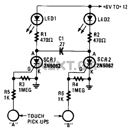
A touch on/off switch circuit is designed using two interconnected sensitive gate SCRs. When one SCR is activated, it forces the other SCR to turn off, creating a toggling effect that allows for an on/off condition for each of...
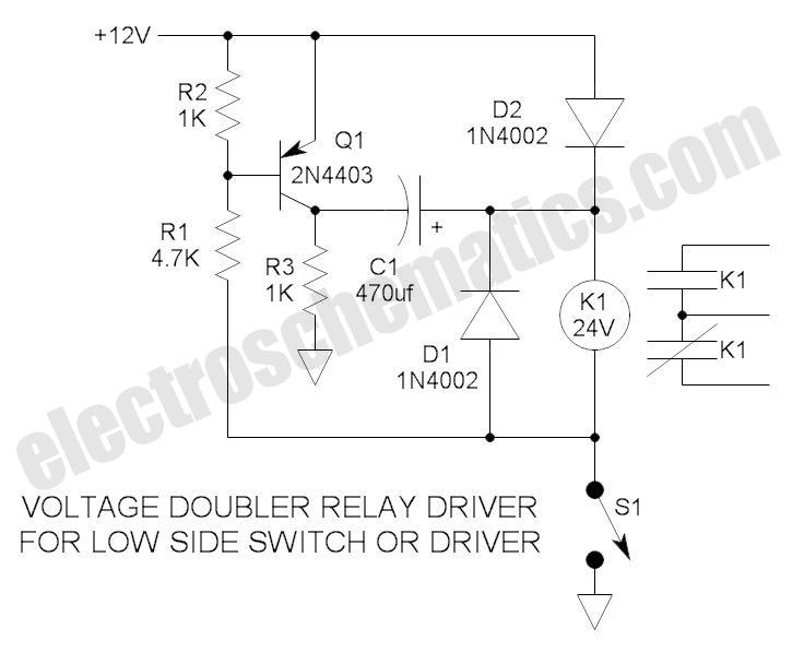
These novel relay driver circuits have the capability to activate a relay with a coil voltage rating that is double the supply voltage (Vcc). Once the relay is activated, the armature is maintained using Vcc, resulting in a significant...
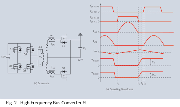
Distributed power systems are commonly used in telecommunications, networking, and high-end server applications, utilizing a 48 V bus voltage derived from the telecom industry. This 48 V bus supplies several isolated point-of-load (POL) converters that power the end loads,...
The project involves designing and constructing a breadboard power supply that draws power from an ATX-like switch-mode power supply (SMPS) using a 4-pin Molex connector. The design features a switch to select either a 12V or 5V output. However,...
Switching Regulator for High Power Efficiency. When it is necessary to convert a high voltage to a significantly lower voltage, a switching regulator is the optimal choice. A switching regulator is an essential component in modern power management systems, particularly...
This circuit can be utilized as a replacement for the single current limiting resistor commonly found in inexpensive battery chargers. The alternative presented here will eventually... This circuit serves as an improved solution for current limiting in battery chargers, particularly...