
on off relay circuit automatic

The NE555 timer is a versatile integrated circuit that can be used in various modes, including astable, monostable, and bistable configurations. In the astable mode, it generates a continuous square wave output, making it ideal for applications requiring periodic signals.
In this circuit, the NE555 timer is connected in such a way that it continuously alternates between high and low states, producing a square wave output. The timing of these states is determined by two resistors and a capacitor connected to the timer. In this specific application, the 100K potentiometer allows for fine-tuning of the timing interval, thereby controlling the frequency of the oscillation. This adjustability is crucial for applications where specific timing sequences are required.
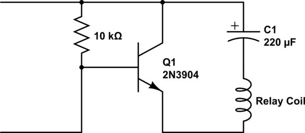
The output from the NE555 timer is fed into the base of the 2N4401 transistor, which acts as a switch to control the 12-volt relay. When the output from the NE555 timer is high, the transistor is turned on, allowing current to flow through the relay coil and activating the relay. Conversely, when the output is low, the transistor turns off, deactivating the relay. This mechanism allows the circuit to control higher power devices or loads that require more current than the NE555 timer can provide directly.
The choice of the 2N4401 transistor is appropriate due to its ability to handle moderate current loads, making it suitable for switching applications in conjunction with the relay. The relay, in turn, can control various types of devices, such as motors, lights, or other electronic components that operate at 12 volts.
Overall, this circuit design exemplifies a practical application of the NE555 timer in an astable configuration, effectively demonstrating how to control a relay using a low-power signal. The adjustable frequency feature enhances the circuit's flexibility, making it applicable for a range of electronic projects and automation tasks.get it on and off continuously. The circuit is using a well known NE555 timer IC which is a very famous IC due to its uses in the wide variety of electronic circuits. In this circuit this IC is connected as a astable multivibator and the 12 volt relay is derived through transistor 2N4401 which is working as a switch.
The ON and OFF rate per second can be controlled by adjusting the 100K pot. 🔗 External reference
Related Circuits
A single-coil latching relay is utilized, which can latch and reset with opposite polarities. Testing of the circuit with dual opposite-biased LEDs showed no flickering in either direction, indicating stable charge and discharge behavior. However, there are concerns regarding...
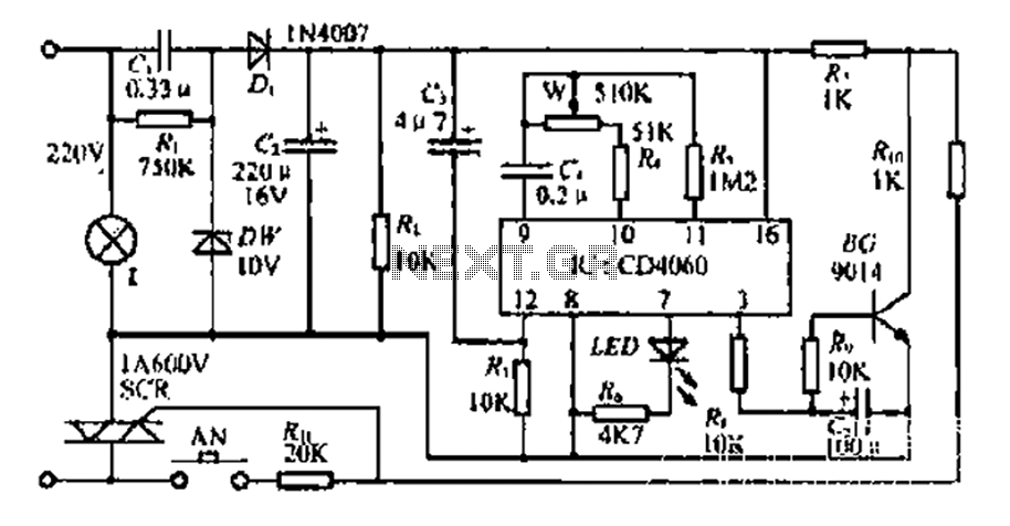
The circuit includes a CD4 component with a connection of 16 feet for the Vcc terminal, 8 feet for the ground, 12 feet for the reset terminal, 7 feet for the Qt end, and 3 feet for the Q...
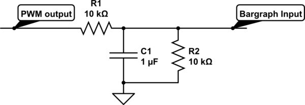
For a project, there is a need to display a progress bar representing the activity performed by a microcontroller unit (MCU). A bar graph display is intended for this purpose; however, the bar graph display driver IC, LM3914, requires...

The FIG load test is a control circuit designed for external loads up to 10A, commonly utilized in drive test power applications, power amplifiers, LED solenoids, and relays. It is capable of handling various resistive loads and features a...
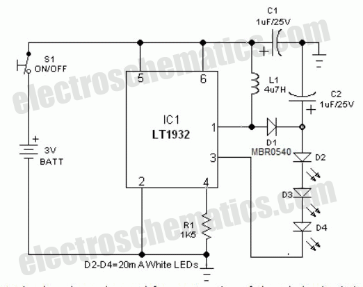
This circuit features a portable solid-state bright light utilizing the LT1932 integrated circuit. It can be powered by two AA dry or rechargeable pen-light batteries. The design allows for customization of the housing, enabling various applications such as a...
This circuit is a simple analog multiplier. The operation of the circuit can be understood by considering A2 as a controlled gain amplifier that amplifies V2, with its gain dependent on the ratio of the resistance of PC2 to...