
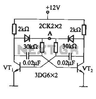
Composition 555 motor automatic governor circuit diagram
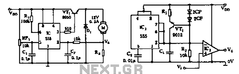
The described circuit utilizes the 555 timer in a motor control application, functioning as an automatic governor. The 555 timer is a versatile integrated circuit commonly used for timing and pulse generation. In this configuration, it operates in a feedback loop with a sampling circuit formed by the resistor R7 and the motor. The motor's operation is monitored through this sampling circuit, enabling the circuit to regulate the motor's speed based on predefined thresholds.
The flip-flops included in the circuit serve to maintain the state of the motor control, ensuring that the motor operates within the desired parameters. The switching tube acts as a control element that can either allow or cut off power to the motor, depending on the output from the 555 timer and the state of the flip-flops.
Adjustment of the trigger sensitivity is achieved through the variable resistor RP1. By altering the resistance, the voltage level at which the 555 timer triggers can be fine-tuned, allowing for precise control over the motor's response to changes in load or speed. This feature is particularly useful in applications where motor performance needs to be optimized for varying operational conditions.
Overall, this automatic governor circuit exemplifies an effective method for managing motor speed and performance, leveraging the capabilities of the 555 timer, flip-flops, and additional components to create a responsive and adjustable control system. As shown is composed of 555 motor automatic governor circuit. The circuit composed of flip-flops 555 and a switch tube. R7 and motor in series to form a sampling circuit. RP1 c ontrol 555 for adjusting the trigger level, ie adjust the trigger sensitivity.
Related Circuits
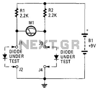
This circuit can be utilized to match diodes for applications where balance is essential, such as in a balanced modulator. The diode matching circuit will display the forward voltage drop of the two diodes in millivolts. The diode matching circuit...
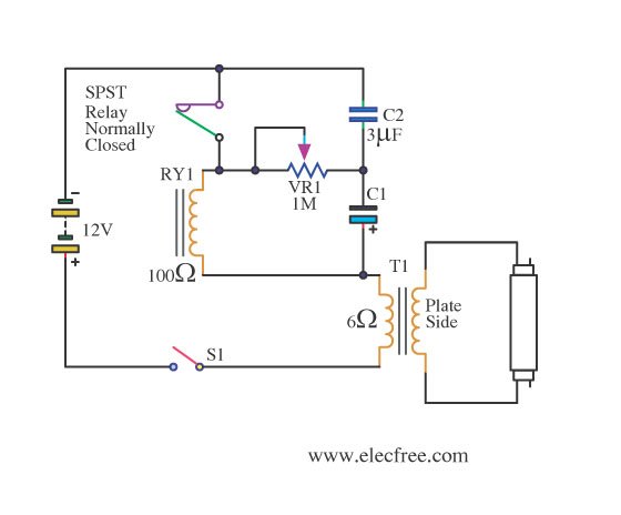
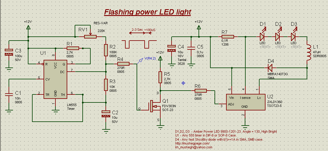
This is a flashing blink circuit designed for 12V applications. It utilizes a small-sized fluorescent lamp and operates through a relay that modifies the circuit from DC to AC. The flashing blink circuit operates at a voltage of 12V, making...
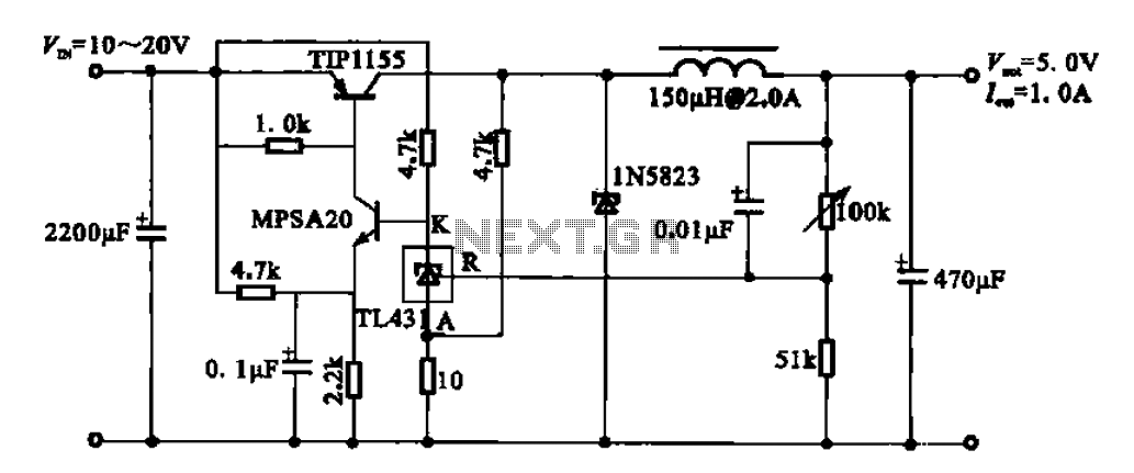
The 5V regulator circuit is designed to convert a DC input voltage ranging from 10V to 20V into a stable 5V output. This circuit features low power consumption and high efficiency. The 5V regulator circuit typically employs a linear voltage...
The circuit illustrated in Figure (A) consists of resistors R1 and R2 with values ranging from 15 to 18 kΩ, and capacitors C1 and C2 with capacitance values between 0.01 µF and 10 µF. Figure (B) depicts the oscillation...
This project demonstrates the construction of a simple flashing light circuit using the IC 555 timer. The 555 timer functions as a clock generator with a duty cycle of less than 100% and greater than 50%. Additional components include...
The audio amplifier circuit is highly suitable for home use, particularly with subwoofer or woofer speakers. Commonly referred to as a home amplifier, these audio amplifiers are based on integrated circuits (ICs), specifically the STK series, which includes models...