
Automatic Turn-Off Alarm With Delay
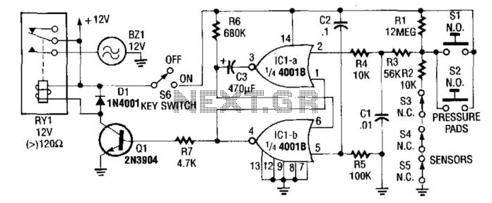
The circuit utilizes two operational amplifiers configured as a monostable multivibrator, where IC1A acts as the trigger input and IC1B serves as the output control. The sensors, designated as SI to S5, are connected to the input of IC1A, which monitors the sensor signals. Upon receiving a valid trigger signal from any of these sensors, IC1A transitions to a logic low state.
This transition causes IC1B to activate transistor Q1, allowing current to flow through the load connected to Q1. The output remains active until capacitor C3, which is charged during the operation, discharges through resistor R6. The time constant for this discharge is determined by the values of C3 and R6, which effectively sets the duration of the output signal from IC1B.
As C3 discharges, the voltage across it decreases, eventually reaching a threshold that resets both IC1A and IC1B. This reset action brings the circuit back to its initial state, ready to respond to the next trigger from the sensors. The design ensures that the output pulse duration can be adjusted by varying the capacitance of C3 or the resistance of R6, providing flexibility in timing applications. The overall functionality is critical in applications requiring precise timing and control based on sensor inputs. In this circuit, IC1A and IC1B act as a monostable multivibrator. Any input from the sensors SI through S5 forces IC1A to produce logic low, which causes IC1B to turn on Ql until C3 changes through R6. This action resets the latch formed by IC1A and IC1B. 🔗 External reference
Related Circuits

Fire alarm circuit using an LDR (Light Dependent Resistor) as a flame sensor. It warns the user about fire accidents by detecting smoke produced during a fire. As smoke passes between an LED and an LDR, the amount of...
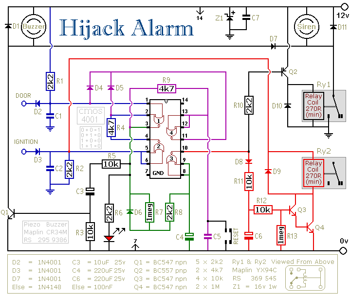
The first circuit was designed for the situation where a hijacker forces the driver from the vehicle. If a door is opened while the ignition is switched on - the circuit will trip. After a few minutes delay -...
The controller circuit illustrated in Figure 15-24 consists of a switch-type Hall integrated circuit DN838 and an astable multivibrator, which is based on the 555 timer IC. This circuit is suitable for various applications, including automatic door opening, delay...

The following circuit illustrates a Wireless Car Alarm Circuit Schematic Diagram. Features include the ability to detect sounds within a 20-meter radius, a 1/16 wavelength antenna, and the capability to transmit radio signals up to 2 kilometers. Q1 serves...

This circuit utilizes a NE555 timer and a CD4020B. When +12 Vdc is applied to the circuit, the output of IC2 is set low via C2, which activates the relay and IC1, functioning as a pulse generator. IC1 generates...
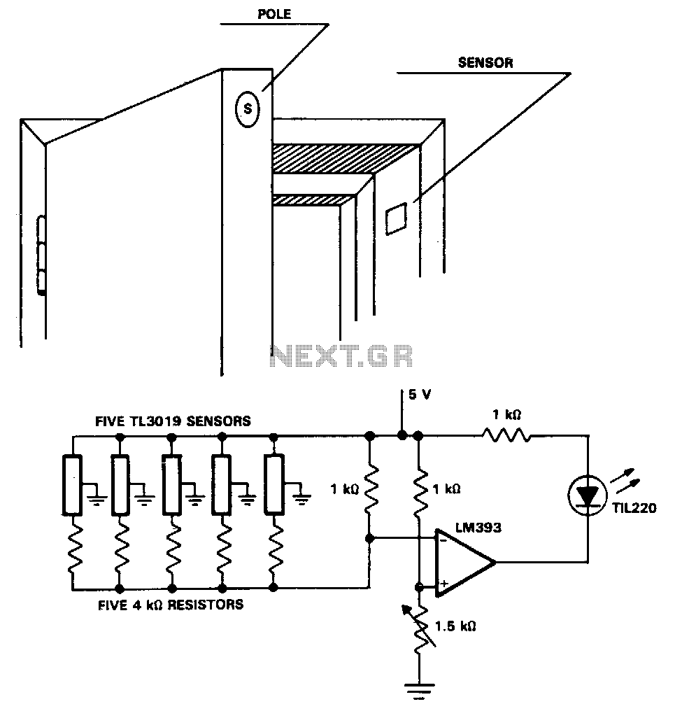
The TL3019 device activates, or goes low, when a south pole of a magnet approaches the chip face. In this example, there are five doors, each equipped with a magnet embedded in its edge, with the south pole facing...