
Two HiJack Alarms
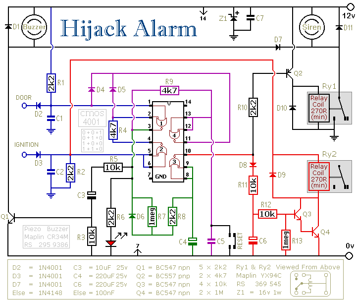
The described circuit functions as an anti-theft system specifically tailored for vehicles. The primary components include a door switch, an ignition switch, a timer, an alarm module, and an engine immobilizer relay.
When the vehicle ignition is active, the door switch is monitored. If the driver’s door is opened, the circuit is triggered, activating a timer. This timer is set to a predetermined delay, typically a few minutes, allowing the hijacker time to distance themselves from the vehicle. During this delay, the system remains in a standby mode, monitoring the status of the door switch.
Once the timer elapses, the alarm module is activated, emitting a loud sound to alert nearby individuals of the theft attempt. Simultaneously, the engine immobilizer relay is engaged, cutting off power to the vehicle's ignition system. This effectively disables the engine, preventing the hijacker from driving the vehicle further.
The design ensures that the system is sensitive enough to respond quickly to unauthorized access while providing a delay that minimizes false alarms due to accidental door openings. The use of a timer allows for a balance between security and practicality, making it an effective deterrent against vehicle theft.
In summary, this circuit is a robust solution that enhances vehicle security by integrating door monitoring, timed alarm activation, and engine immobilization to thwart potential theft attempts.The first circuit was designed for the situation where a hijacker forces the driver from the vehicle. If a door is opened while the ignition is switched on - the circuit will trip. After a few minutes delay - when the thief is at a safe distance - the alarm will sound and the engine will fail.
🔗 External reference
Related Circuits
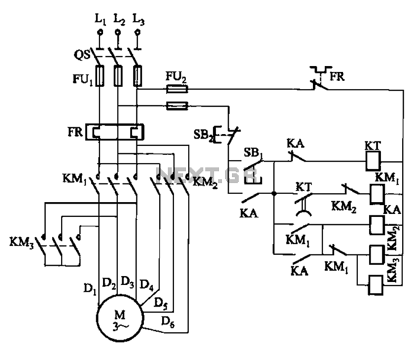
The circuit depicted in Figure 3-99 illustrates a low start-up mechanism for a motor, which transitions to high-speed operation automatically. The start-up process is facilitated by a shaped connection, while the transition to high-speed operation is managed by a...
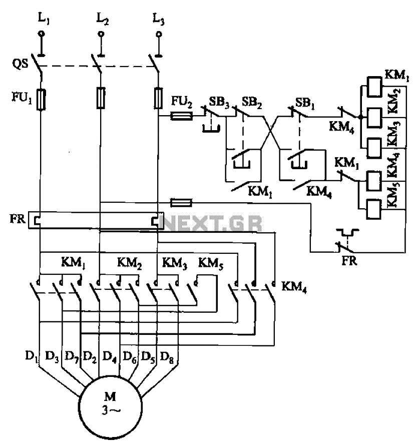
The circuit illustrated in Figure 3-104 features SB2, which functions as the low-speed operation button, and SBi, which serves as the high-speed operation button. The circuit design utilizes two distinct operational buttons, SB2 and SBi, to control the speed of...
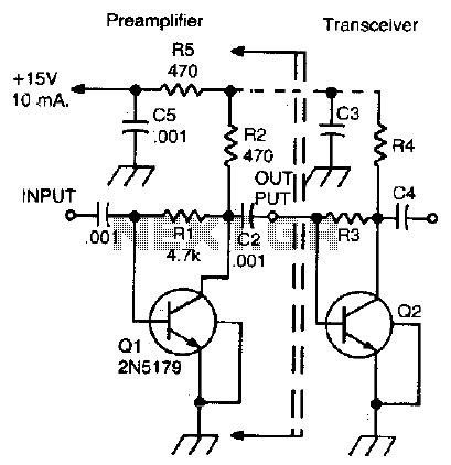
This simple, inexpensive, wideband RF amplifier provides 14 dB gain on two meters without the use of tuned circuits. The RF amplifier described operates within the two-meter band, which typically spans frequencies from 144 to 148 MHz. It is designed...
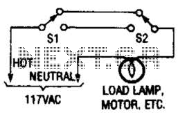
This switching arrangement is utilized in both domestic and industrial environments to enable control of a light or other AC-operated device from multiple locations. This switching arrangement, commonly referred to as a multi-way switching system, is designed to facilitate the...
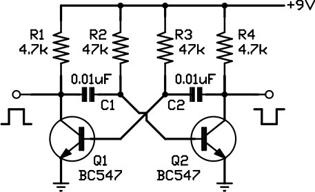
This circuit is one of the simplest to implement but can be challenging to comprehend. It consists of a two-transistor oscillator known as an astable multivibrator, which generates a square wave output that is out of phase. Initially, it...
Flying hand launch gliders necessitate the use of small-capacity receiver NiCad battery packs. While these lightweight packs are advantageous, they have the significant drawback of quickly depleting. Although careful timing of flights can be employed, it often results in...