
AM circuit ring
The AM diode ring modulator circuit operates by utilizing four diodes configured in a circular arrangement, which enables effective mixing of the input signals. Each diode in the ring contributes to the modulation process, allowing for the combination of low-frequency audio signals with high-frequency carrier waves. The diodes are essential in shaping the output waveform, ensuring that the amplitude of the carrier signal is altered according to the amplitude of the modulating signal.
The specified diode model, 2AP9, is selected for its favorable characteristics in terms of forward voltage drop and switching speed, making it suitable for high-frequency applications. The resistive components, with values of 100Ω and 470Ω, serve to stabilize the circuit and optimize performance by providing necessary biasing and load conditions. These resistors help to ensure that the diodes operate within their optimal range, minimizing distortion and enhancing the fidelity of the output signal.
The output signal Qi produced by the circuit is a modulated waveform that retains the information of the original audio signal while being transmitted at a higher frequency. The design's simplicity is advantageous, as it reduces the complexity of the circuit and the potential for errors during assembly. Additionally, the low harmonic output contributes to a cleaner signal, which is crucial in communication systems where clarity is paramount.
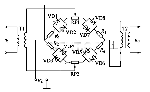
This diode ring modulator circuit is often integrated into larger systems, such as radio transmission and reception modules, where compactness and efficiency are essential. Its balanced and symmetrical output characteristics make it an ideal candidate for integration into ICs, allowing for mass production and reliability in various electronic applications.AM diode ring circuit consists of four diodes to form a ring road, so called diode ring modulator circuit. AM diode ring circuits greater advantages. Due to the characteristics of the diode and discrete circuits, etc., often have to use resistive element correction circuit, the circuit shown
in actual annular AM diode VD are 2AP9. Other device parameters reference values: resistance; Ri = R2 = Ra = R4 -l OOtl, RRPI -Rr {PZ-470fl. Diode ring circuit low-frequency modulation signal amplitude and high frequency carrier signal by the high-frequency amplitude modulation circuit converting the signal output Qi. The amplitude modulation circuit is simple structure, less harmonic output, good balance and symmetry, often used in the form of an integrated circuit.
Related Circuits
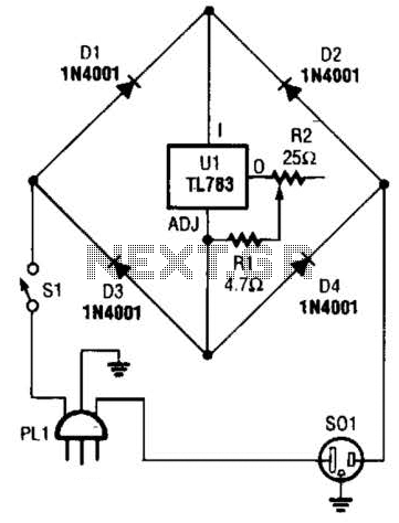
A current control circuit for temperature regulation of a soldering iron utilizes a high-voltage integrated regulator, TL783 (U1). With the specified component values, this circuit is suitable for use with a soldering iron rated at 25 W or less. The...
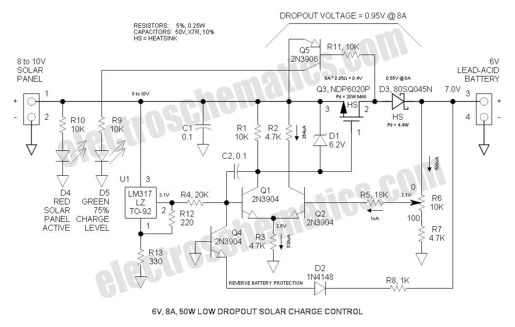
This Low Dropout Voltage (LDO) solar charge controller utilizes a straightforward differential amplifier combined with a series P-channel MOSFET linear regulator, ensuring compatibility and efficiency in solar energy applications. The Low Dropout Voltage (LDO) solar charge controller is designed to...
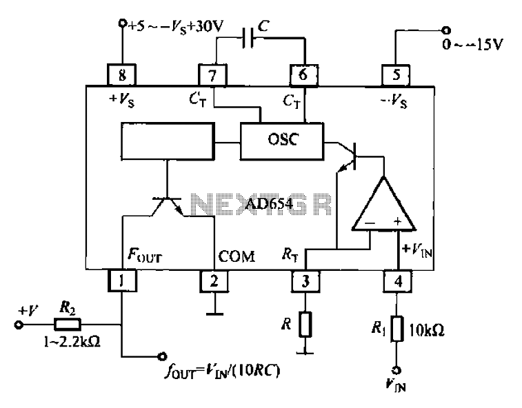
The AD654 voltage-frequency converter is a low-cost device that operates with a single supply voltage ranging from +5V to +36V, as well as with dual supplies of +5V to +18V. It can handle a maximum input voltage of 36V...
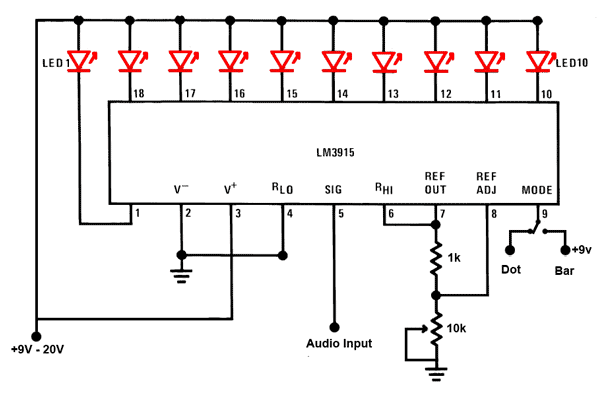
This is a simple audio sound level LED display circuit diagram. The circuit is entirely based on a single integrated circuit, the LM3915 from National Semiconductor. The LM3915 is a monolithic integrated circuit that displays the audio sound level...
Servo motors are utilized in various applications, including robotics, puppetry, photography, and more. These compact motors can adjust their output shaft to a specified position on command and maintain that position. Most servos offer a range of motion of...
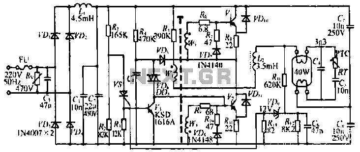
The figure illustrates the input from the varistor, which serves an overvoltage protection role. Components VDi and VD4 function as rectifiers, while L1 and C2 are utilized for filtering. The circuit comprises R, C9, and VD6, which are part...