
Automatic washing machine motor driver schematic

The automatic washing machine motor driver schematic serves as a comprehensive representation of the control mechanisms involved in the operation of the Narcissus XQB30-III-type washing machine. The circuit's design integrates various components to ensure efficient motor control and water management during the washing process.
The four Triacs in the circuit are responsible for switching the motor's power supply, allowing for precise control of the motor's operation in both forward and reverse directions. This is critical for the washing and rinsing cycles, as the motor must operate in both directions to effectively agitate the laundry. The drive transistors amplify the control signals from the microcontroller, ensuring that the Triacs are triggered appropriately based on the washing program selected.
The microcontroller plays a central role in the operation of the washing machine. It processes inputs from the water level sensor and foot switch to regulate the solenoid valve's operation, ensuring that water is only added to the tub when necessary. The control logic embedded in the microcontroller dictates when to stop water intake, activate the motor, and manage the drain cycle effectively.
Transistors VT3 and VT4 are pivotal for determining the motor's direction. Depending on the washing program, the microcontroller activates one of these transistors to either forward or reverse the motor's rotation. This functionality is essential for the washing process, as it allows for thorough cleaning of the clothes through agitation.
At the end of the wash cycle, the microcontroller signals the motor to stop by turning off VT3 or VT4. It then activates VT5 to engage the drain solenoid valve, allowing water to exit the tub. The timing of these operations is carefully managed to ensure that the washing machine operates efficiently and effectively.
Finally, the inclusion of a buzzer, activated by transistors VT7 and V12, serves as an alert to the user that the washing cycle has completed. This feature enhances user experience by providing audible feedback on the machine's status. Overall, the schematic illustrates a well-coordinated system that integrates various electronic components to deliver a reliable and effective washing machine operation. Automatic washing machine motor driver schematic It shows the automatic washing machine motor drive circuit schematic. The circle of Narcissus XQB30-III-type washing machine mo tor drive circuit practical. The control circuit is composed of four Triac, four drive transistor and the control chip consisting of a base of the transistor save when there is a high level, it is turned on, the corresponding thyristor is triggered, controlled electromagnetic Kui move oak. At the start of washing, the water level microcomputer program controller foot switch connected to the water level and switch (Hang foot water solenoid valve work together to control the washing water injection barrel.
When the water level reaches a predetermined level, the process microcomputer program controller inlet valve control transistor VT6 deadline to stop injecting water to the wash tub. microcomputer program controller or the foot of transistor VT3 or VT4 conduction, the motor forward or reverse, start washing clothes.
wash Xie after completing microcomputer control device or (Liao foot transistor VT3 or VT4 close, the motor stops running computer control emblem pin din transistor. VT5: conduction, drain solenoid valve begins to work when the drain to the end. one minute, microcomputer program controller feet transistor VT7 and V I2 is turned on, the buzzer start crying.
Related Circuits
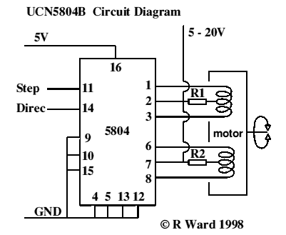
This integrated circuit is highly efficient and does not require any external glue logic for operation. It features two pins for motor control: one pin is dedicated to controlling the direction of the motor, while the other pin is...
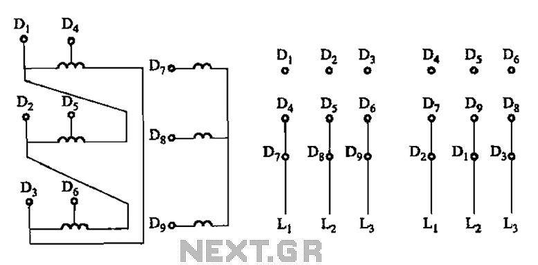
The connection of the lead wires from the stator winding of a two-speed motor to the coils is illustrated in Figure 3-109. The schematic representation of the two-speed motor's stator winding connection is critical for understanding its operational characteristics. In...
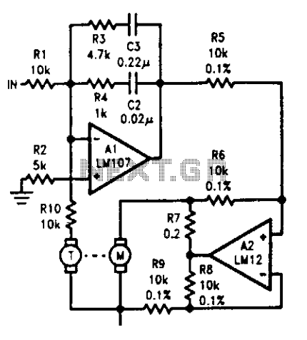
The tachometer, mounted on the same shaft as the DC motor, functions as a generator, producing a DC output voltage that is proportional to the motor's speed. A summing amplifier, labeled as Al, manages its output to ensure that...
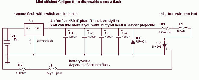
This is a fun and non-dangerous project for those people who like to throw projectiles magnetically. It simply works by placing a ferromagnetic projectile at one end of a coil and pulsing some power in it. The trick is...
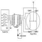
The simplest method to drive a stepper motor with a lower current rating is by utilizing the ULN2003. The ULN2003 consists of seven Darlington transistors and can handle up to 500mA per channel, with an internal voltage drop of...
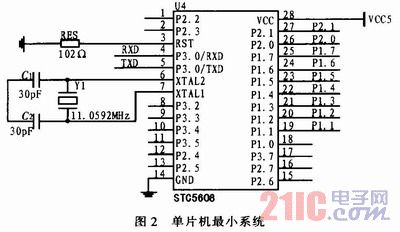
The widespread application of Surface Mount Technology (SMT) in products such as computers, network communications, consumer electronics, and automotive electronics has led to increasingly complex, high-precision, and multifunctional electronic assemblies. Accurate testing techniques can enhance manufacturing efficiency and ensure...