
unipolar stepper motor controller

The integrated circuit in question is designed to facilitate the operation of stepper motors, which are commonly used in applications requiring precise control of angular position. The two control pins simplify the interface, eliminating the need for additional components typically required for motor control, such as logic gates or microcontroller outputs.
The direction control pin allows for easy reversal of the motor's rotation, enabling applications that require bidirectional movement. The pulse triggering pin generates the necessary stepping signals, which dictate the speed and position of the motor. By adjusting the frequency of the pulses sent to this pin, the speed of the stepper motor can be finely tuned to meet specific operational requirements.
This integrated circuit supports various configurations of stepper motors, including 5, 6, and 8 wire types. The ability to drive different motor configurations enhances its versatility, making it suitable for a wide range of applications, from robotics to CNC machinery. The compact nature of the design also contributes to space-saving in electronic assemblies, making it an ideal choice for modern, compact devices.
In summary, this integrated circuit provides an efficient and straightforward solution for driving stepper motors, offering enhanced control with minimal external circuitry. Its design allows for a seamless integration into various electronic systems, ensuring reliable performance in demanding applications.This is a very good integrated circuit. There is no need for any external glue logic to drive the circuit, there is only 2 pins to drive the motor, one for controlling the direction and the other to trigger the stepping pulses. It provides a very compact design that drives 5 or 6 or 8 wire stepper motors.. 🔗 External reference
Related Circuits
The TRW-24G connector pins are quite small, approximately 1mm apart. To address this issue, an adaptor PCB has been ordered to convert the small connector of the RF module to a standard pin connector. The pin arrangement of the...
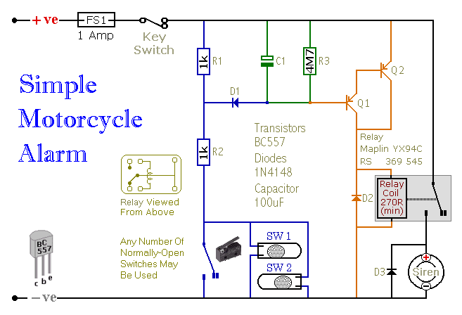
Motorcycle Alarm Number 4. This is a simple, easy-to-build, transistor-based motorcycle alarm. It is designed to operate at 12 volts; however, it can be adapted by changing the relay to a different specification. This motorcycle alarm circuit utilizes a transistor...
It was discovered through experience why the 6V EQ-5 hand controller should not be connected to 12V by mistake. It only took about half a second to damage the hand controller. Upon inspection, it became clear that the large...
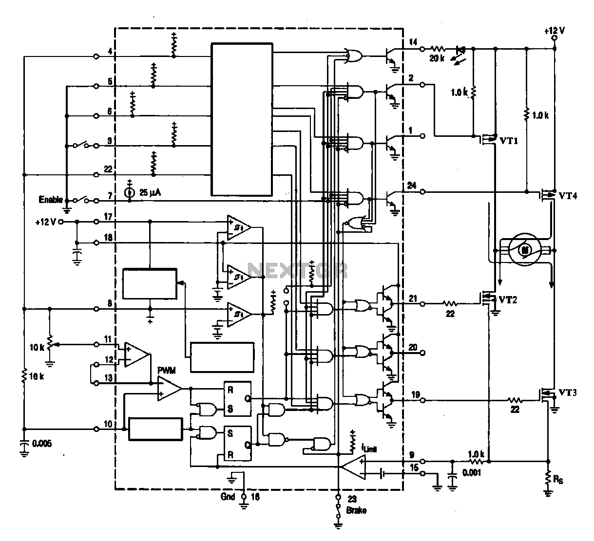
A DC brush motor driver circuit diagram utilizing the MC33035 chip is presented, illustrating a typical configuration for driving a straight DC brush motor. The circuit incorporates a field-effect transistor (FET) bridge driver setup. When transistor VT3 is activated,...
Again, using the versatile IC 741. The feedback of this IC are two T-filters included the strengthening of the treble and bass influence. P1 is responsible for regulating the bass and treble controls P2. Where P1 to the direction...
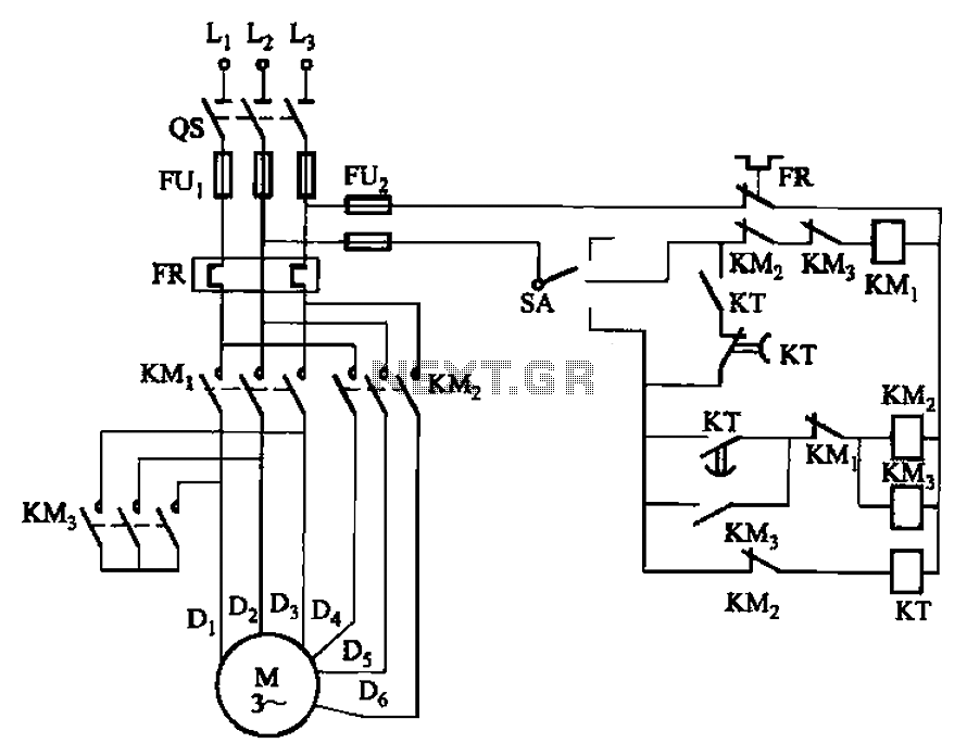
The circuit depicted in Figure 3-98 demonstrates how motor starting and low-speed operation are managed using switch SA. By adjusting the time relay KT, the motor's operation can transition from low speed to high-speed operation within a specified time...