
Automatic winding circuitry
The electronic winding machine incorporates a sophisticated design tailored for efficient operation in winding applications. The core of the system is the optical sensor circuit, which employs resistors (R1, R2, R3, R4) and optical couplers (VLC1, VLC2) to detect the winding process. This circuit is divided into two main functions: the addition counting circuit and the subtraction counting circuit. The addition circuit is triggered by the first optical sensor (VLC1), which detects the winding motion and activates the counter to increment the count. Conversely, the subtraction circuit is initiated by the second optical sensor (VLC2), which is used for reverse winding operations, allowing the system to decrement the count as needed.
The shaping circuit is constructed using a Schmitt trigger NAND gate integrated circuit (IC1), which stabilizes the signal and ensures reliable operation during the counting process. The plus/minus recognition circuit employs two D flip-flops (IC2) to manage the direction of the count, allowing for seamless transitions between winding and unwinding operations.
The four-digit counter is a crucial feature, consisting of a counter/decoder integrated circuit (IC3 to IC6) that drives a digital display (LEDs A to D). This display provides real-time feedback to the operator regarding the number of turns completed. The reset functionality is integrated into the circuit, allowing the operator to clear the count as needed. The system is designed for user-friendly operation, with adjustments available for the resistors (Ri, Rz, R3) to fine-tune the sensitivity of the optical sensors, thereby accommodating various winding materials and conditions.
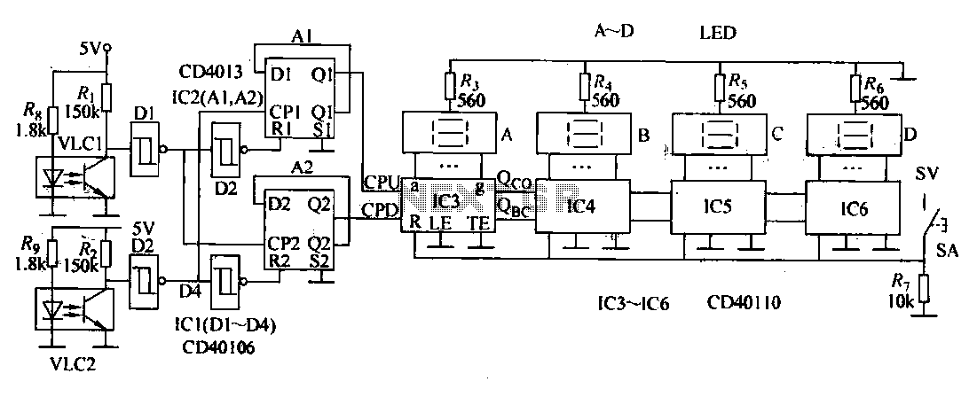
Overall, this electronic winding machine exemplifies advanced engineering design, combining electronic counting capabilities with mechanical winding processes to enhance production efficiency and accuracy in motor winding applications.Electronic Winder points manual, electric, semi-automatic winding machine variety, this example describes a winding machine with electronic counting feature that lets users coi led, used motor windings. (1) The circuit Winder shape as shown in FIG. 7-la. By the optical sensor circuit, shaping circuit, plus/minus recognition circuit and four-digit counter circuit, as shown in Figure 7-lb. Photosensor circuit consists of resistors Ri, R2, flat, R, and optical coupler VI-C1, VI4C2 composition.
R., R. And VLC1 composition adder counting sensor circuit. Rz, R9 and VLC2 composition subtraction counting sensor circuit. South Sixth shaping circuit Schmitt trigger NAND gate integrated circuit lCl internal rhyme D1-D4 constitute. Plus/minus recognition by the two D flip-flop circuit IC2 internal trigger Al, A2 components. Four-digit counter by the resistors R3-R, reset button S, counter/decoder integrated circuit IC3 ~ IC6 and LED digital display A ~ D components.
(2) The circuit diagram used to answer it SA, to reset the counter is cleared, then the input Dl, D3 and D2, D4 of the output terminal are high. Oi, Q2 output of IC2 is low. 10 does not count. When the winding machine forward (addition count), the rectangular aperture winding turntable so VLC1 first trigger, so D1 output high.
D2 output low Subsequently VLC2 trigger, D3 output level as the end of IC2 CP1 trigger pulse, A1 stupid turn in lC3 {the CPU side to join the count pulse, the counter starts counting the addition. Similarly, if the winding reverses, then. VLC2 first trigger work, VLC1 trigger work. AZ flip, count pulses IC3 provide the CPD, subtraction counter starts counting. Adjustment Ri wind resistance, can change VLC1 sensitivity. Adjustment Rz and R, the resistance, can change VLC2 sensitivity. Automatic winding machine has counted five simultaneous winding coils and other functions, can improve production efficiency.
Related Circuits
As shown in the generator start battery automatic monitor circuit diagram. The generator start battery automatic monitor circuit is designed to oversee the battery's status during generator operation. This circuit ensures that the battery remains charged and functional, preventing premature...
This circuit is designed for a project utilizing a 6V, 400 mA DC power supply. The open-circuit voltage is specified, indicating the voltage measured when no load is connected. The circuit employs a regulated 6V power supply, which is essential...

This design is for a charger circuit suitable for lead-acid batteries, including flooded, gel, and AGM types. The circuit features a simple design. The automatic function means that this charger will stop charging automatically when the battery voltage reaches...
This circuit project automatically activates a night lamp when the bedroom light is turned off. The lamp stays illuminated until the light sensor detects daylight. The circuit operates using a light-dependent resistor (LDR) as the primary sensor to detect ambient...
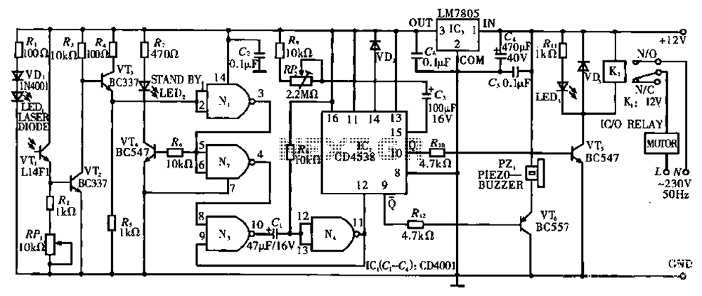
Circuit T operates on the principle of utilizing a laser diode LED as a light emitter. This circuit incorporates a laser diode that serves similar functions as a light-emitting diode. It features a resistor (R) and a diode (VD)...
Currently, batteries are becoming increasingly powerful, serving as the sole energy source for portable electronic devices. The rapid evolution of battery technology has prompted manufacturers of electronic equipment to strive for reduced power consumption in their products, enabling them...
Warning: include(partials/cookie-banner.php): Failed to open stream: Permission denied in /var/www/html/nextgr/view-circuit.php on line 713
Warning: include(): Failed opening 'partials/cookie-banner.php' for inclusion (include_path='.:/usr/share/php') in /var/www/html/nextgr/view-circuit.php on line 713