
Open doors and windows automatic laser beam control circuit
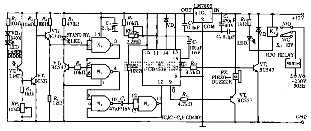
The described circuit T employs a laser diode LED as a primary light source, functioning effectively as both a laser and a light-emitting diode. The inclusion of a resistor (R) and a protection diode (VD) is crucial for safeguarding the laser diode from current surges, which could otherwise damage the component. The multi-loop trimming potentiometer (RP) serves as an adjustable element, allowing users to fine-tune the sensitivity of the laser detection system according to specific requirements or environmental conditions.
In operation, when the laser beam is directed towards the phototransistor (VT), it triggers conduction in the device. This conduction results in a zero base potential at VT3, indicating that the phototransistor is effectively responding to the laser light. The emitter of VT3 also reaches a zero potential, which is then fed into the first gate of the CD4001 integrated circuit. The logic gate interprets this zero potential as a high output signal.
The high output from the CD4001 is pivotal for the subsequent operation of the circuit. It facilitates the conduction of transistor VT4, which is connected in such a way that it can amplify the output signal. The conduction of VT4 leads to the activation of a green LED, providing a visual indication of the system's readiness or standby state. This feature enhances user interaction by signaling that the circuit is operational and awaiting further input.
Overall, Circuit T exemplifies a well-designed electronic system that integrates a laser diode, phototransistor, and logic gate to create a responsive light detection mechanism. The careful selection of components and the inclusion of protective measures ensure reliability and functionality in various applications. Circuit T as principle: In this circuit, a laser diode LED, as a light hair emitter, in addition to other properties may also be used similar light emitter laser diode substitu tion pipe. Resistor R. And diode VD, as the laser diode current protection circuit, multi- loop trimming potentiometer RP, for adjusting the sensitivity of the laser. Under normal circumstances, when a laser beam is irradiated to a phototransistor VT. When on, VTz conduction, VT3 base potential is zero (VL zero bias), VT3 deadline, its emitter potential is zero.
The zero potential applied to the IC. (CD4001) first gate N, the input of the results of N. The output is high. But also through the high resistance of the transistor VT4 added to the base so that VT4 conduction, so that the green LED, lights up. In this case the circuit is in a standby state waiting.
Related Circuits
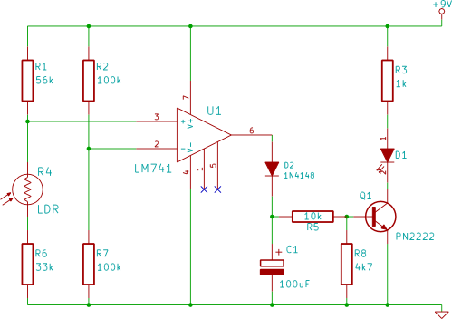
This electronic breadboard circuit for beginners in electronics activates an LED automatically when the ambient light level falls below a specific threshold. This circuit utilizes a light-dependent resistor (LDR) as the primary sensor to detect ambient light levels. The LDR...
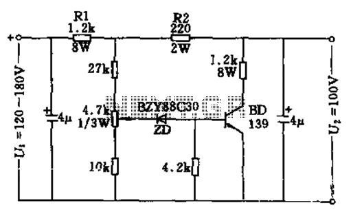
The circuit features no-load and short circuit protection mechanisms. To accommodate short circuit conditions, it is necessary to increase resistors R1 and R2 to allow for power dissipation; for example, R1 can be set to 1.2kΩ with a power...
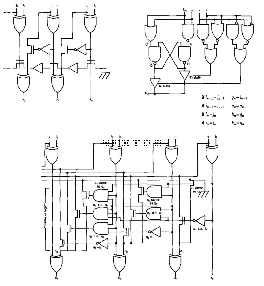
Some circuits that add binary numbers experience time delays due to carry propagation. This issue has been partially addressed by the carry look-ahead adder. However, the complexity of this method typically limits its application to no more than 4...
This presence detector or proximity sensor circuit responds to the presence of any conductive object, including humans. The sensitivity can be adjusted with potentiometer P1, which is positioned at a considerable distance from the rest of the circuit. This...

This musical light alarm circuit is very simple and uses only seven components, including a light-dependent resistor (LDR) and a 3.6V battery or three 1.2V rechargeable batteries. The well-known UM66 is utilized as the sound generator, providing a pleasant...
This is a light sensor circuit designed to detect light and activate a relay. The circuit is straightforward and requires only a few components. The operation of the circuit is simple: when the photoresistor detects light, it will turn...