
automatic 12v lead acid battery charger

The charger circuit operates by employing a voltage regulation mechanism to ensure that the charging voltage remains within the specified limits for different types of lead-acid batteries. The use of a potentiometer (R2) allows for fine-tuning of the cut-off voltage, which is critical for maintaining battery health and longevity. The design incorporates an automatic shut-off feature that is activated once the battery reaches the predetermined voltage, preventing overcharging. This is essential for lead-acid batteries, as overcharging can lead to gassing and damage.
The LED indicator serves a dual purpose: it provides a visual confirmation of the charging status and indicates when the battery is fully charged. This feature enhances user convenience and safety, allowing users to monitor the charging process without needing to check the voltage manually.
The inclusion of a heat sink for the transistor (Q1) is crucial, as charging processes can generate significant heat, especially under high load conditions. The option to add a fan powered by the output of the rectifier (D1) ensures that the circuit remains within safe operating temperatures, thereby enhancing reliability and performance.
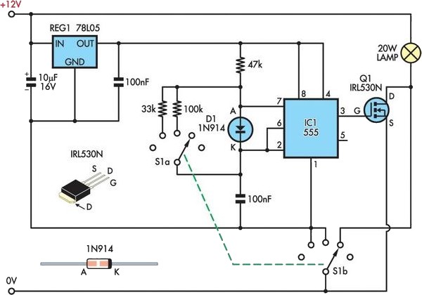
Finally, the recommendation to disconnect the battery when the circuit is powered off is a critical safety measure. This prevents the risk of slow discharge, which can lead to battery damage if the voltage drops below the safe threshold. Properly implementing these design considerations will result in a robust and efficient charger circuit for various lead-acid battery types.This is design for charger circuit that is suitable for lead-acid battery, including flooded, gel, and AGM types. This circuit is simple design. This is the figure of the circuit. The automatic term means that this charger will stop charging automatically when the battery voltage reach a certain pint, indicating that the battery has been fully cha
rged, and charging will be restarted if the battery voltage falls below that threshold. A LED indicator is provided to show you when the battery is fully charged. This automatic battery charger can be left connected to a battery indefinitely to maintain full charge safely. 1. R2 is used to adjust the final voltage when the charger should stop charging. For flooded and gel type, the batteries are usually charged to 13. 8V. For cycling the battery (AGM or gel), 14. 5V to 14. 9V is usually recommended by battery manufacturers. Set the R2 pot to midpoint, turn on the charger and connect a battery to its output. Monitor the charge with a voltmeter until the battery reaches the proper end voltage, then adjust the pot until the LED glows constantly.
To charge different types of batteries, you can mount the pot on the front of the case and mark each position of every battery types ending voltage. 2. Install proper heat sink for Q1. A small fan might be necessary and can generally be powered right off the output of D1 If the circuit is mounted in a case.
4. If the circuit is powered off, you should disconnect the battery because the circuit will drain the battery slowly, and this could damage your battery if the battery is drained while it`s voltage falls below about 10V. 🔗 External reference
Related Circuits
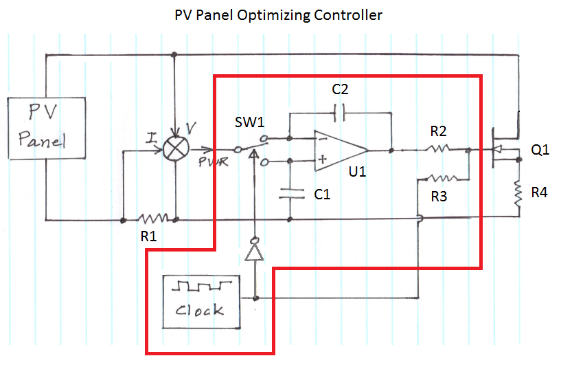
The figure illustrates the voltage-current (V-I) curve for a typical solar panel (Sharp ND-224U1F) and its output power under varying lighting conditions. The solar panel operates as a constant current source at high currents and as a voltage source...
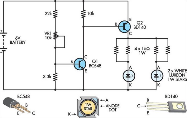
This circuit replaces two white Luxeon 1W Star LEDs for the inverter and fluorescent tube in a standard battery-powered illuminated exit sign, commonly found in commercial buildings. Although the Luxeon LEDs produce less light output than a typical small...
Mobile phone chargers available in the market are quite expensive. The circuit presented here serves as a low-cost alternative to charge mobile telephones or battery packs with a rating of 7.2 volts. The proposed circuit design utilizes a straightforward approach to...
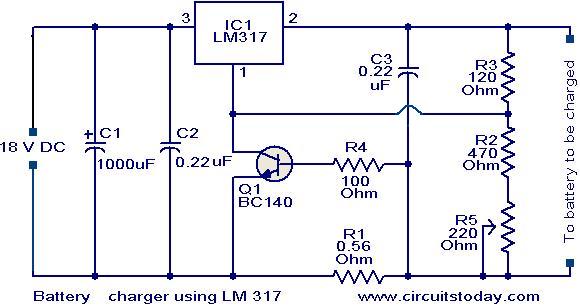
This is a simple yet effective battery charger circuit utilizing the LM317 integrated circuit (IC). The circuit is designed for charging 12V lead-acid batteries and can be easily assembled on a general-purpose printed circuit board (PCB). The core component...
The objective is to add a security sensor light near the main entrance that operates on 12 volts. While 12-volt PIR sensors are available, they tend to be costly, often exceeding $50 each and are specifically designed for security...
A 12V 20W halogen lamp (MR16) is utilized in a bike light system powered by a 4.2Ah SLA battery. Due to the limited battery life at this power rating, a cost-effective light dimmer has been designed to reduce battery...