
Automatic Wiper Control Circuit using NE 555 IC
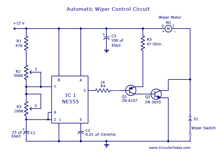
The circuit utilizes the NE 555 timer IC configured in astable mode to control the operation of a windshield wiper motor. The primary function of this circuit is to provide an adjustable intermittent wipe feature, allowing the wipers to operate at a set interval, specifically every 10 seconds.
In this design, the NE 555 generates a square wave output that drives a transistor, which acts as a switch for the wiper motor. The frequency of the square wave is determined by the values of two resistors (R1 and R2) and a capacitor (C1) connected to the 555 timer. The duty cycle can be adjusted by varying the resistance values, which in turn changes the time the wipers are on and off.
The circuit is powered by the vehicle’s battery, typically at 12V, and includes components such as diodes for flyback protection to prevent back EMF from damaging the circuit when the motor is turned off. Additionally, a potentiometer may be included in the circuit to allow for fine-tuning of the delay interval based on user preference.
This design not only enhances the functionality of the windshield wipers but also contributes to safer driving conditions during inclement weather by ensuring optimal visibility through controlled wiper operation.A circuit for car windshield/wiper motor speed control built using NE 555 IC.This enables intermittent windshield wiper control which changes sweep rate to 10 seconds.. 🔗 External reference
Related Circuits

The transmitter is constructed on a Printed Circuit Board (PCB). This board incorporates track inductors for L1, L2, and part of L3. The section surrounding Q1 functions as the oscillator section, with the oscillation frequency determined by L1, C4,...
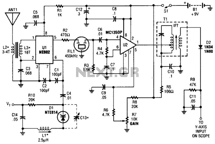
This circuit is designed for monitoring an amateur band or a specific segment of the radio spectrum. It utilizes an NE602 mixer-oscillator chip to generate a 455-kHz intermediate frequency (IF) signal. This signal is amplified by U2 and subsequently...
The configuration presented in the diagram below is a simple MOSFET-based design intended for amplifying current at ±60 volts, allowing the connected transformer to generate a required output of 1 kVA. The components Q1 and Q2 form the initial...
A simple FM transmitter connects a home entertainment system to a portable radio that can be moved around the house and into the backyard. For instance, music can be played from a CD player in the living room and...
The loop can be any type of hookup wire, with a maximum resistance of about 90K. Using very thin wire (40AWG, for example) will create a highly sensitive trip wire, but will reduce the distance it can be strung...
A programmable clock timer circuit that utilizes individual LEDs to indicate hours and minutes. Twelve LEDs can be arranged in a circle to represent the twelve hours of a clock face, while an additional twelve LEDs can be arranged...