
Diagram description GPS support kit
The GPS interface is designed to accommodate two distinct power supply configurations, enhancing its versatility in various applications. The first configuration utilizes a stabilized 5V supply, which is ideal for direct connection to devices that require a consistent voltage level. The second option allows for a broader input range of 10 to 25V from an unregulated DC supply, making it suitable for environments where voltage levels may fluctuate.
Power is introduced to the circuit through an RJ45 connector, specifically at pin 8, ensuring a standardized connection method that is commonly used in networking equipment. The ground reference for the power supply is established at pin 7, providing a common return path for current and ensuring proper operation of the circuit.
To protect the circuit from overcurrent conditions, a slow-blow 315mA fuse is incorporated into the design. This fuse is strategically placed within a socket, allowing for easy replacement in the event of a fault. The slow-blow characteristic is crucial for applications where inrush currents may temporarily exceed the fuse rating without causing it to blow, thus maintaining circuit functionality during normal operation.
In addition to the fuse, a Transzorb device is connected to ground, serving as a protective measure against voltage transients. This device is specifically designed to clamp reverse polarity voltages and voltages that exceed 27V, effectively preventing damage to the GPS module and associated circuitry. In the event of a fault, the Transzorb facilitates a short circuit condition that triggers the fuse to blow, thereby isolating the affected section of the circuit and safeguarding the remaining components.
Overall, this design emphasizes reliability and protection, ensuring that the GPS interface can operate safely under varying power supply conditions while minimizing the risk of damage from overvoltage or reverse polarity scenarios.The GPS interface can be fed in 2 ways: with a stabilized 5V supply or with a 10 to 25V unregulated DC supply. In both cases the power is fed into the RJ45 connector on point 8. Pin 7 is DC ground. The power supply current is first secured with a slow 315mA fuse (in socket). Then there is a Transzorb device to ground. This device is a short-circuit for reverse polarity voltages and for voltages above 27V. It causes the fuse to blow and in doing so, protecting the other electronics and GPS module. 🔗 External reference
Related Circuits

A simple instrumentation amplifier circuit diagram utilizing an operational amplifier (op-amp). The equation for gain, along with design, working principles, and construction details, are also provided. An instrumentation amplifier is a type of differential amplifier that has been designed to...

The chip power later, when the strobe IEB is held low, allows for the transfer of memory to the instruction, address, and read or write data. All operations regarding order, address, and data transfer initiate from the least significant...
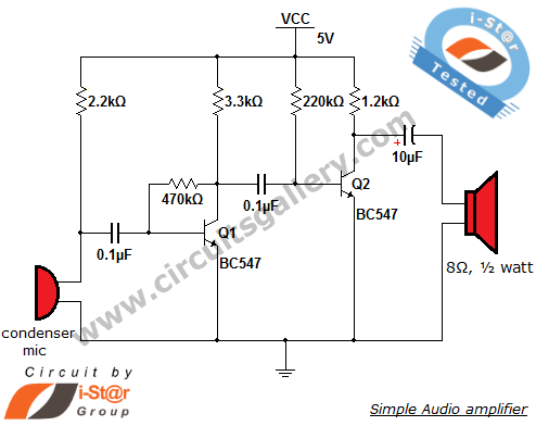
The output of the condenser microphone is coupled through a 0.1 µF coupling capacitor, which serves to eliminate DC components from the audio signal. Transistor Q1 is configured in a collector-to-base biasing mode, achieved with a 470kΩ resistor. This...
%2BCircuit%2Bdiagram%2Busing%2BCD4047%2Band%2BIRFZ44%2Bpower%2BMOSFET.png)
This simple low-power DC to AC inverter circuit converts 12V DC to either 230V or 110V AC. By making simple modifications, it is also possible to convert 6V DC to 230V AC or 110V AC. This inverter can be...
The count switching circuit consists of an electronic switch and a pulse delay circuit for control. The count switching circuit is designed to manage the switching of signals in a controlled manner. The electronic switch serves as the primary component...
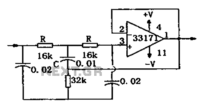
The trap circuit utilizes a high-performance operational amplifier, MC33171, to create the trap. This device features a wide bandwidth and high conversion rate. The component values can be modified by adjusting the capacitance of capacitor C and the resistance...