
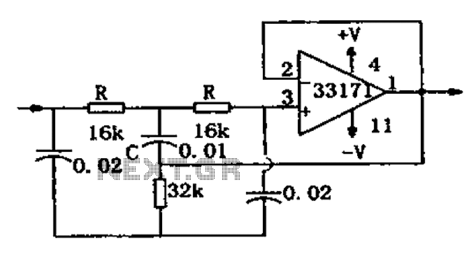
Notch filter circuit diagram MC33171
The trap circuit is designed to selectively filter out specific frequencies from a signal while allowing other frequencies to pass through. The MC33171 operational amplifier serves as the core component due to its excellent performance characteristics, including a high slew rate and low noise, which are essential for maintaining signal integrity in high-frequency applications.
In this circuit, the notch frequency can be adjusted by varying the values of the capacitor C and the resistors R. The formula for the notch frequency, f = 1/(4RC), indicates that the frequency response of the circuit is inversely proportional to the product of the resistance and capacitance values. Therefore, increasing the capacitance or resistance will lower the notch frequency, while decreasing these values will raise it.
The design typically consists of a feedback loop that incorporates the operational amplifier, capacitor, and resistors. The configuration ensures that the desired frequency is attenuated while minimizing the impact on adjacent frequencies. The high-performance characteristics of the MC33171 allow for precise tuning and effective filtering, making this trap circuit suitable for applications in audio processing, communication systems, and signal conditioning.
Overall, this trap circuit exemplifies the application of operational amplifiers in electronic filtering, demonstrating how component selection and configuration can be leveraged to achieve specific signal processing goals. As shown for the trap circuit. The circuit uses a high-performance op amp device MC33171 constitute trap. The device has a wide band and a high conversion rate. In the illustra ted component values by changing the value of a capacitor C and two resistors R, and other available notch frequency, its value is: f 1/4 RC.
Related Circuits
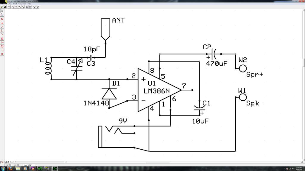
Initially, the individual has limited experience in electronics. They constructed a crystal radio circuit using components salvaged from a non-functional radio, including an LM386N audio amplifier. A crystal radio circuit is a simple radio receiver that operates without the need...
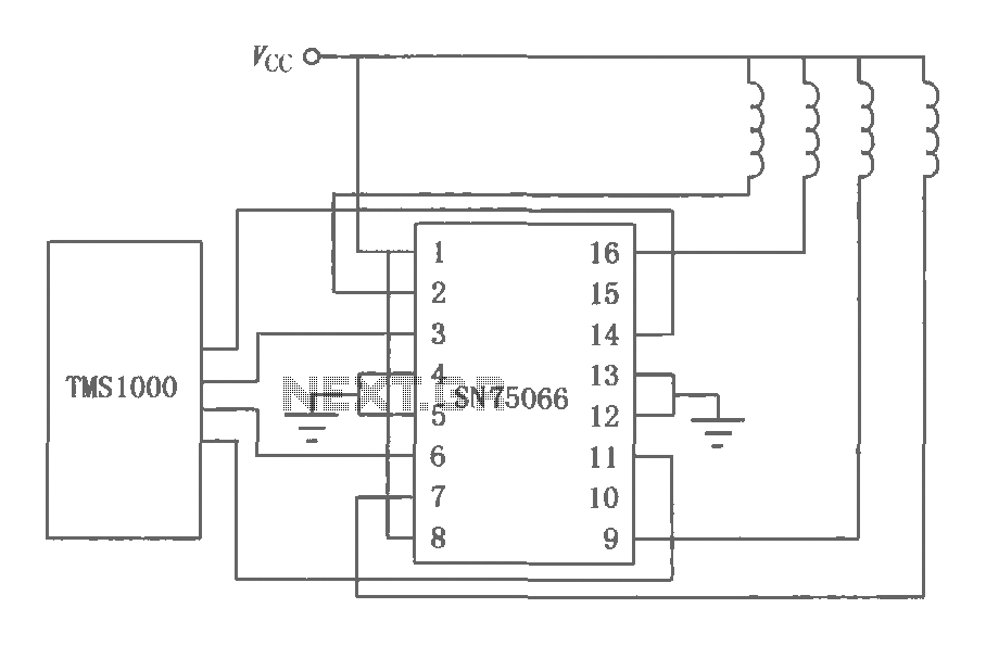
The SN75064 to SN75067 series consists of monolithic, high-voltage, high-current Darlington switch output terminations. These devices include clamp diodes, making them suitable for inductive loads. Each package contains four Darlington pairs that can be connected in parallel to achieve...
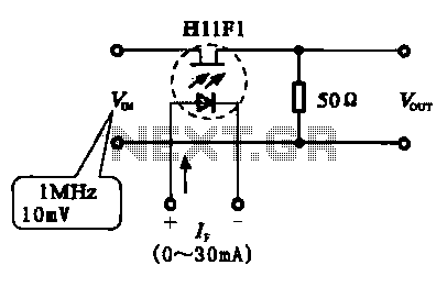
A phototransistor, also referred to as a photosensitive transistor, is primarily utilized as a photosensitive device. It is characterized by its ability to adjust impedance in relation to the intensity of incoming light, similar to that of photosensitive resistors...
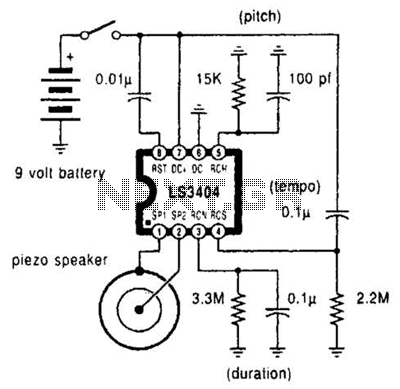
A high-quality melody circuit produces a slow decay waveform that generates chime-like notes. The pitch, tempo, and duration of the notes are all adjustable. The melody circuit is designed to offer a versatile sound generation capability, making it suitable for various...
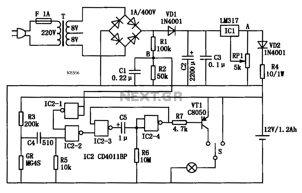
An automatic multipurpose emergency lights circuit is presented. Typically, emergency lights are connected to the mains for standby when fully charged. In the event of a sudden power failure, the ambient light transitions from strong to weak, indicating a...
This circuit is designed to detect microwave sources, such as microwave ovens, satellite communication devices, and mobile phones. It provides audio-visual indications upon detecting microwaves in the gigahertz band, which encompasses frequencies between 2 GHz and 300 GHz. Microwave...