
DC motor speed control circuit diagram of a song
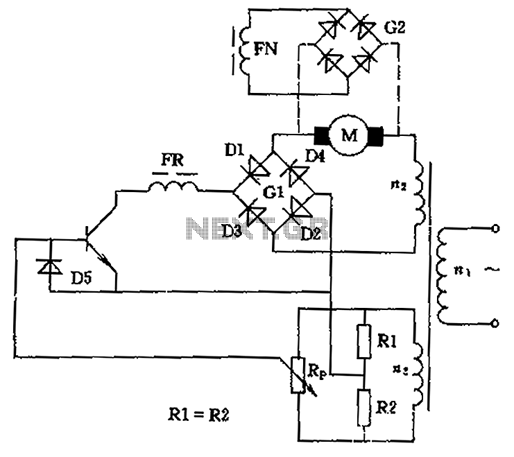
The circuit employs a rectifier bridge configuration (G1) to convert AC voltage from the transformer’s secondary winding into a usable DC voltage for the motor. This rectification process is crucial for providing a steady and reliable power supply to the motor, which is essential for consistent speed control. The control mechanism is further enhanced by the use of a sliding contact potentiometer (Rp), which functions as a variable resistor. Adjusting the position of the sliding contact alters the resistance in the circuit, thereby modifying the voltage supplied to the motor.
When the sliding contact is positioned at the midpoint, the circuit effectively disconnects the motor, stopping its operation. This feature serves as a safety mechanism, preventing unintended motor activation. Conversely, moving the sliding contact in either direction allows for the adjustment of motor speed and direction. The upward movement increases the voltage, causing the motor to rotate in the forward direction, while downward movement decreases the voltage, reversing the motor's rotation.
In practical applications, this circuit can be implemented in various settings, including robotics, conveyor systems, and other automated machinery where precise motor control is necessary. The design ensures that operators can easily manage the motor's performance, providing flexibility and adaptability to different operational requirements. Overall, this circuit represents a robust solution for controlling low-power DC motors with both speed and directional capabilities, making it a valuable component in electronic control systems. Circuit can be used to control low power DC motor, series motor or shunt motor speed and direction. Motor and rectifier bridge G1 series, and then connected to the grid transfo rmer secondary winding n2. If the output of the rectifier bridge fails, the motor stops, which is equivalent to the sliding contact potentiometer Rp in the middle position, if the upward or downward movement of the sliding contact, the motor will forward or reverse, it can control the motor operation.
Related Circuits
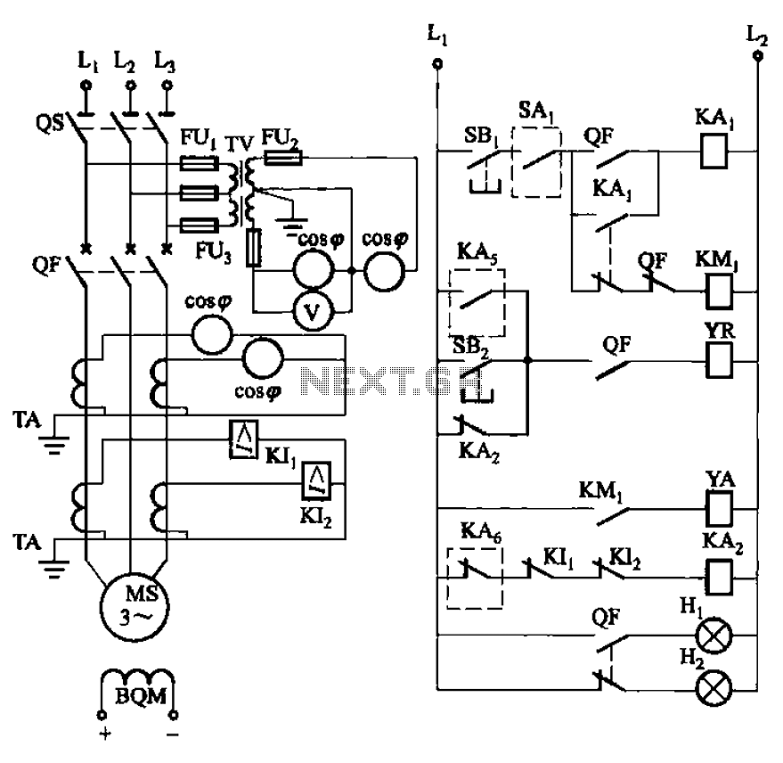
The circuit depicted in Figure 3-186 includes an isolation switch, QF vacuum circuit breakers, YR line for the circuit breaker coil, and YA for the circuit breaker closing coil. Additionally, there is a dashed box representing the excitation device...
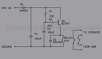
This circuit was designed for an audio amplifier project to control the speaker output relay. The primary function of this circuit is to manage the relay that activates the speaker output in the audio amplifier. The circuit introduces a...
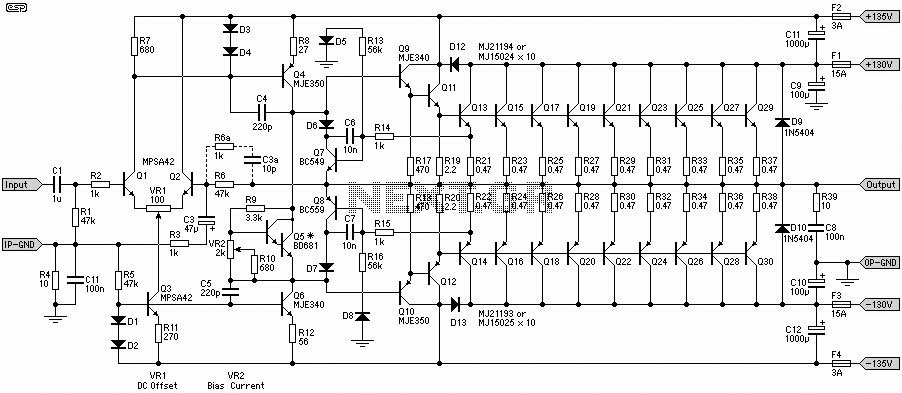
This 1500W Power Amplifier Circuit Diagram contains two images of the circuit. For more complete information, refer to the main post titled "1500 Watt Power Amplifier." It includes a list of component parts for the 1500W Power Amplifier Circuit...
Incorporate resistors in a parallel configuration to enhance audio input. To control the volume for each input channel, integrate a linear trimmer or potentiometer with the following configuration: pin 1 connects to ground, pin 2 serves as the output,...
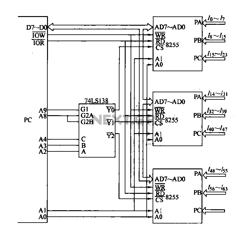
The computer control system is designed to detect signal path switching, requiring multiple input interface expansions. This system can switch all signal inputs into the computer. By utilizing a programmable chip, the 8255 expansion input interface allows for three...
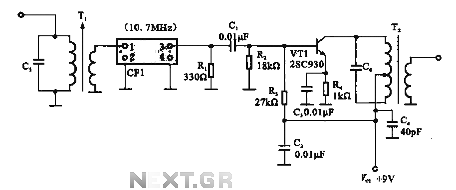
This circuit features a ceramic filter integrated with an FM intermediate frequency (IF) amplifier. The FM IF amplifier circuit primarily consists of an input variable voltage regulator (T), ceramic filters (CF1), and additional components such as the IF amplifier...