
Multifunctional motor protection circuit

The circuit's design is centered on monitoring and rectifying AC signals to provide a stable DC output suitable for further processing. The use of IC4 as a signal processor allows for effective signal conditioning, ensuring that the input from the resistive divider (R2 and RP) is accurately represented. The half-wave rectification process is critical for transforming the AC signal into a usable DC form, which is achieved through the action of diodes VD7 and VD6. These diodes only allow one polarity of the AC signal to pass, effectively blocking the negative half-cycle and enabling the circuit to utilize only the positive portion of the waveform.
The capacitors C7 and C1 play a crucial role in smoothing the rectified output, reducing ripple and providing a more stable DC voltage to the load. The resistors R3 to Rg are involved in setting the gain and establishing the reference voltage levels necessary for the A/D conversion process. The output at R8, along with the capacitors, ensures that the voltage remains within the acceptable range for the A/D converter, thus enabling accurate digital representation of the current being monitored.
This circuit is particularly useful in applications requiring precise current measurements in three-phase systems, such as electric motor protection. By continuously monitoring the current in each phase, the circuit can detect anomalies or faults, allowing for timely intervention to prevent damage to the motor. The inclusion of an LED display provides a visual indication of the current levels, making it easier for operators to assess the system's status at a glance. Overall, this design exemplifies a robust solution for current monitoring and motor protection in industrial applications.Circuit works: When normal inspection work where the voltage across the resistor R2 through, RP, partial pressure, as the input signal of IC4. IC4, R3 ~ Rg, C7 ~ ~ Cl ,, VDs VD, and the like mean response of a half-wave rectified linear AC / DC converter amplifier. Positive half cycle, signal flow is: IC4 a CS island a VD7- R6_ + _ + RP2- GND. The negative half cycle, the current discharge circuit is: GND- * RP2- R7- VD6_ Cs- lC4. Outputs R8, cl ,, Rg obtained an average RMS input linearly proportional DC voltage, the voltage by S.
(S. placed in normal operation measuring end) into the A / D converter is adjusted correctly IC ,, R) l and RP2, can accurately display LED current transformer primary current of BT. When used to protect the three-phase AC electric motor, which can be used to detect electrical circuit motive in any phase of the three-phase current.
Related Circuits
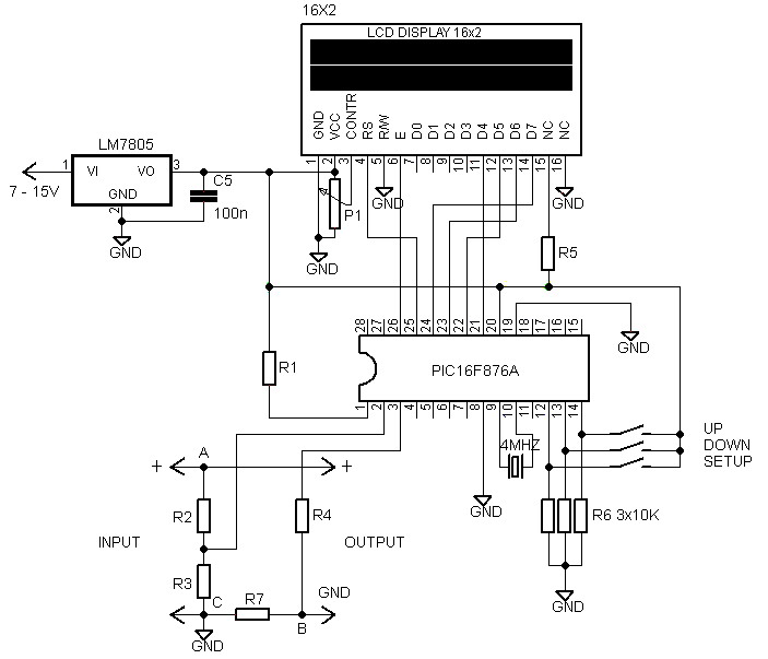
A voltmeter and ammeter using a PIC microcontroller can measure voltage and current simultaneously. This setup employs a PIC16F876A as the data processor for voltage and current measurements. An LCD display (16x2) is utilized to present the measured voltage...
Telephones are declining globally; however, India has over 350 million mobile phone users, alongside a significant number of traditional telephone users. This telephone timer is designed to save costs by controlling unnecessary time spent during phone calls. This simple...
This audio noise filter circuit functions as a bandpass filter specifically designed for the audio frequency range. It effectively filters out unwanted signals that fall below or above the desired audio frequencies. The circuit comprises two filters: a low-pass...
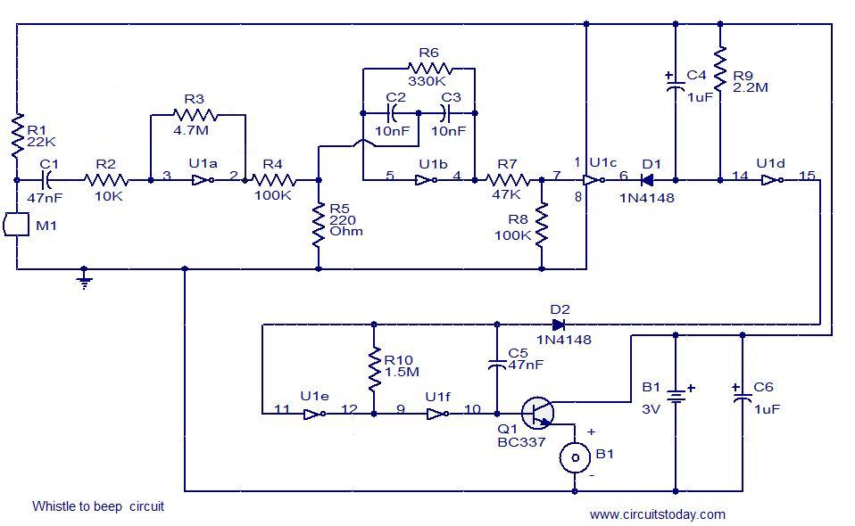
This simple circuit produces a beeping sound that lasts for approximately 3 seconds whenever a whistle is made. The CMOS Hex inverter CD4049 serves as the core component of this circuit. Among the six inverters in the CD4049, U1a...
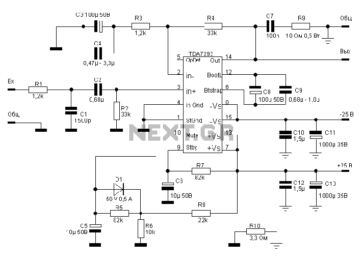
The TDA7293, produced by the ST (SGS-THOMSON) company, is a high-power, high-voltage DMOS high-fidelity amplifier integrated circuit (IC) with a rated output power of 100W. It operates at a maximum voltage of 120V. The key specifications include a dual...
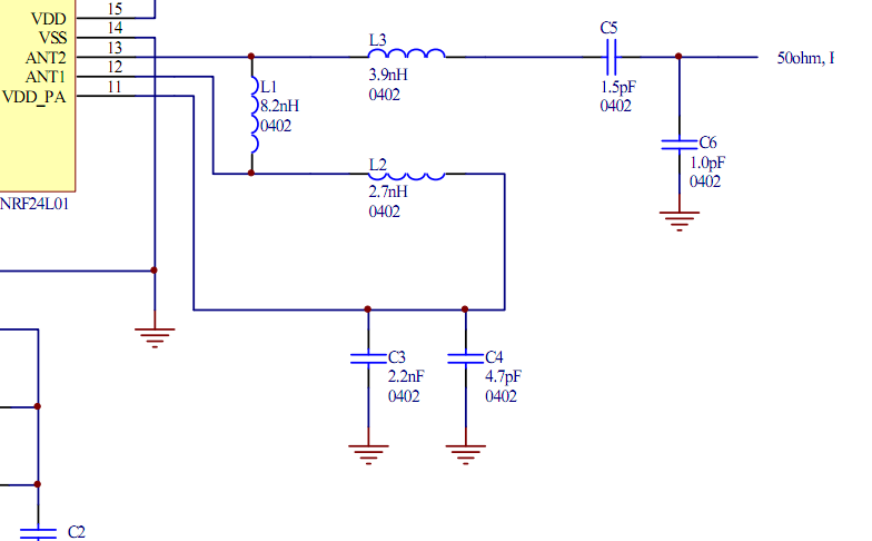
Place the transceiver and the chip antenna very close together, eliminating the need for a 50-ohm transmission line. If this is the case, can the two matching circuits be merged into one to reduce the component count? To create an...