
rf Can I merge two impedance matching circuits
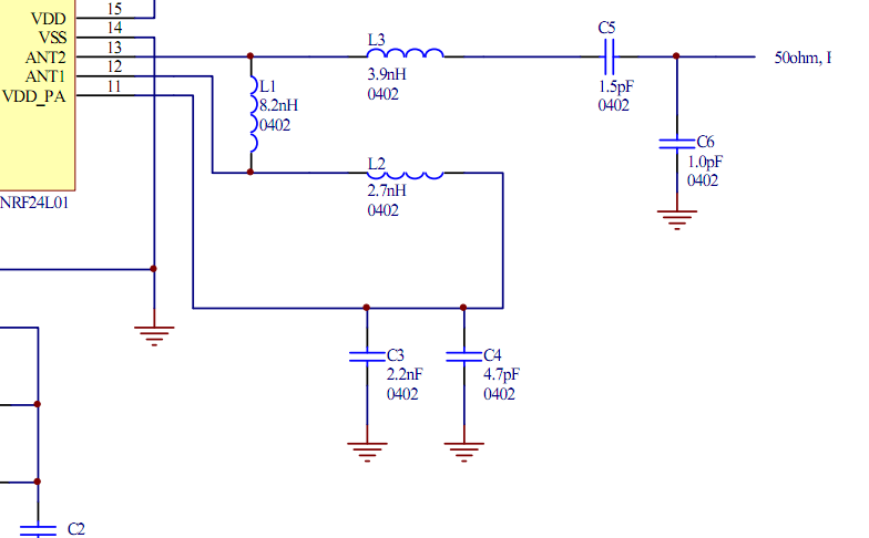
To create an efficient RF circuit, positioning the transceiver and the chip antenna in close proximity is essential. This arrangement can significantly simplify the design by negating the requirement for a 50-ohm transmission line, which is typically used to match the impedance between the transceiver and the antenna.
In this scenario, merging the matching circuits of both components can be achieved through careful impedance matching techniques. The goal is to ensure that the output impedance of the transceiver aligns with the input impedance of the chip antenna. This can be accomplished using a combination of reactive components such as capacitors and inductors to form a matching network that optimally transforms the impedance.
For practical implementation, a common approach is to utilize a L-network or a pi-network configuration. An L-network consists of one inductor and one capacitor, while a pi-network includes two capacitors and one inductor. The choice between these configurations depends on the specific impedance values that need to be matched and the frequency of operation.
When designing the matching network, simulations can be conducted using software tools like ADS (Advanced Design System) or LTspice to analyze the performance and ensure the desired impedance transformation is achieved across the operational frequency range. Additionally, attention should be given to the physical layout of the circuit, as parasitic capacitance and inductance can affect performance.
By merging the matching circuits, a reduction in the component count is possible, leading to a more compact design, lower manufacturing costs, and improved reliability. However, it is crucial to verify that the merged circuit still meets the necessary performance specifications, such as return loss and insertion loss, to ensure efficient signal transmission and reception.Place the transciever and the chip antenna very close, then there is no need for a 50 ohm transmission line right If so, can I somehow merge those two matching circuits into one and thus reducing component count 🔗 External reference
Related Circuits

Below 10 MHz, the development of engineering models is relatively straightforward and not significantly influenced by printed circuit board layout. In the VHF range, parasitic circuit elements and unwanted coupling can severely impact efforts to achieve cost-effective performance without...
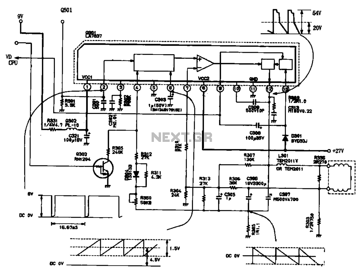
The field scanning circuit generates sawtooth waveforms essential for color television field scanning. The circuit, as illustrated in Figure 1, is utilized in the Toshiba 2150 TV. The vertical scan pulse signal is produced from the LA7837 integrated circuit,...
This discussion continues from the audio tone control topic, which introduced both passive and active tone controls. The follow-up topics may include a 2-Band Active Tone Control or a 3-Band Active Tone Control. An audio equalizer is utilized to...
The previous tutorials on SPICE simulation in Fedora Electronic Lab have introduced various concepts. This post focuses on Part 3, assuming familiarity with gschem and completion of a course on analog electronic circuits. It is advised to review the...
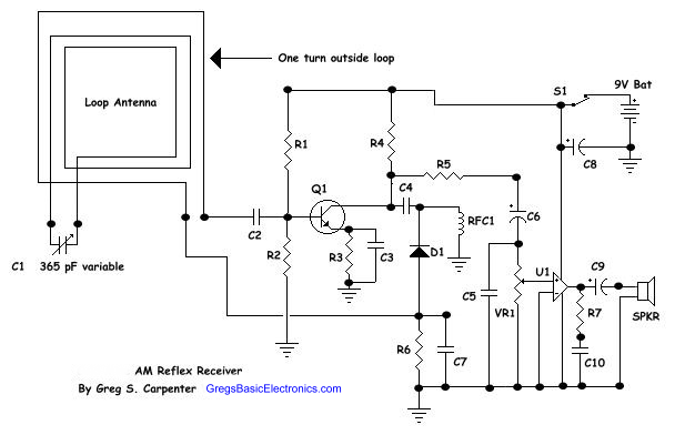
AM radio receivers demodulate amplitude-modulated (AM) signals. The primary source of these signals is the Standard AM Radio Broadcast Band, although shortwave stations also utilize AM modulation. Amplitude modulation was developed between 1900 and 1917 by amateur radio enthusiasts....
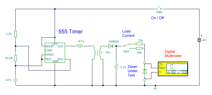
This circuit utilizes a single 555 Timer IC along with a small transformer to generate high voltage for testing zener diodes with voltage ratings up to 50VDC. The 555 timer operates in astable mode, with the output from pin...