
Simple PWM controller
The circuit utilizes a 555 timer IC configured in astable mode to generate a pulse-width modulation (PWM) signal. The core functionality of the PWM controller is achieved through the manipulation of the resistor R1 and capacitor C1, which determine the duty cycle of the output signal. The duty cycle, which ranges from 0% to nearly 100%, is adjustable by varying the value of R1. The frequency of the PWM signal is primarily influenced by the values of R1 and C1, with a calculated frequency range of approximately 170 Hz to 200 Hz for the specified component values.
The 555 timer operates with a supply voltage typically between 4.5V and 15V, making it versatile for various applications. The output from the 555 timer can drive loads directly or can be interfaced with additional circuitry, such as transistors or MOSFETs, to control larger loads. The use of standard diodes, such as the 1N4148, is sufficient for this application, as they are not critical to the circuit's performance, allowing for flexibility in component selection.
To implement this PWM controller, it is necessary to connect the timing capacitor C1 between pin 6 and ground, while pin 2 is connected to pin 6 to provide feedback for the timing cycle. The resistor R1 is connected from pin 7 to the supply voltage, and a second resistor (not mentioned in the description but typically required) connects pin 7 to pin 6. The output can be taken from pin 3 of the 555 timer, which provides a square wave signal with varying duty cycle based on the configuration of R1 and C1.
This PWM controller can be utilized in various applications, including motor speed control, light dimming, and signal modulation, making it a cost-effective solution for projects requiring adjustable duty cycle signals. The total cost of components being approximately $2 highlights the affordability of implementing this circuit in practical applications.This 555 timer based PWM controller features almost 0..100% pulse width regulation using R1, while keeping the oscillator frequency relatively stable. The frequency is dependent on values of R1 and C1, values shown will give a frequency range from about 170 to 200 Hz.
Any 555 chip will do, CMOS is fine as well. Diodes are not critical, I used 1N4148. Total cost of parts is about $2. 🔗 External reference
Related Circuits
The Flip-Flop Robot drives forward until it encounters an obstacle, at which point it reverses until it strikes another obstacle. This back-and-forth motion continues indefinitely. By simplifying the functionality to this basic behavior, the robot can be constructed using...
A slice of the SM2965 includes a canonical 80C32 microcontroller, FLASH memory, E2PROM (28SF512), SRAM for static data storage, and a watchdog timer (WDT). The cost performance of the SM2965 is notably high. This device is designed as a...
Connection of a drive and a two-phase hybrid stepper motor using a four-wire system, with the motor windings configured in both parallel and series connections. This method allows for high-speed performance, although it requires a large drive current (1.73...
The simple mixer schematic is based on the common base principle, where input voltages are transformed into alternating currents that are summed to form the output. The simple mixer circuit utilizes the common base configuration of a transistor, which is...
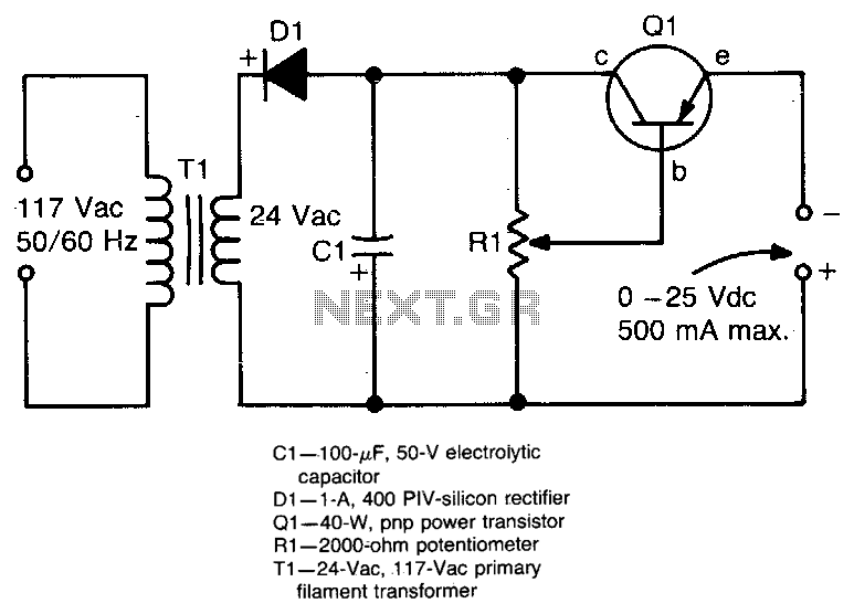
This circuit provides an adjustable output voltage of up to 35 V DC with a maximum output current of 50 mA. The transistor Q1 dissipates significant heat and must be mounted on a heatsink. The circuit in question is designed...
Tro telephones can be utilized as an intercom through the implementation of this circuit. Traditional rotary phones, particularly those that are non-electronic, may be the most effective for this purpose. Additionally, this method can also power handsets alone. The circuit...