
Simple mixer circuit

The simple mixer circuit utilizes the common base configuration of a transistor, which is characterized by its ability to handle high-frequency signals and provide low output impedance. In this configuration, the emitter terminal serves as the input, while the collector terminal is the output. The base terminal is typically grounded or connected to a reference voltage, allowing the input signals to be applied directly to the emitter.
In operation, two or more input voltage signals are fed into the emitter of the transistor. These signals are transformed into alternating currents, which are then combined or summed at the collector. The summing process effectively allows for the mixing of different frequencies, making it suitable for applications in audio processing, radio frequency (RF) communications, and other signal processing tasks.
The output from the collector can be further processed or amplified, depending on the requirements of the application. The choice of transistor, along with the biasing resistors and coupling capacitors, plays a crucial role in determining the performance characteristics of the mixer, including gain, bandwidth, and distortion levels.
In summary, the simple mixer schematic based on the common base principle provides a straightforward yet effective method for combining multiple input signals into a single output, making it a valuable component in various electronic systems.The simple mixer schematic is built on common base principle, where input voltages are transformed in alternative currents wich are summed to form the alte. 🔗 External reference
Related Circuits
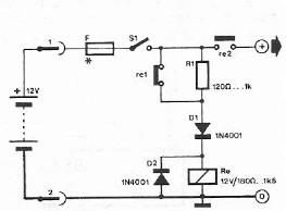
Safety polarity connection circuit design using common electronic components The safety polarity connection circuit is designed to ensure that electronic devices are connected with the correct polarity, preventing damage from reversed connections. This circuit typically employs common electronic components such...

The touch sensor switch circuit diagram features a step-down rectifier circuit, a 555 timer, and flip-flops. When a hand touches the metal sheet A, the sensor signal activates the internal comparator of the 555 timer, setting the output to...
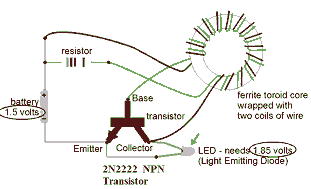
This circuit is known as the Joule Thief. For those unfamiliar with it, an image of the circuit is provided. The Joule Thief is a minimalist circuit designed to extract usable voltage from a low-voltage power source, such as a...
In addition to its primary function as a headphone amplifier, this circuit is applicable in various scenarios requiring a wide bandwidth low power amplifier. It utilizes an operational amplifier (op-amp) with its output current enhanced by a pair of...

The single transistor connected between the capacitor and the common side of the AC line allows a logic-level signal to control this TRIAC power circuit. Resistor R2 prevents false triggering of the TRIAC by the trickle current through the...
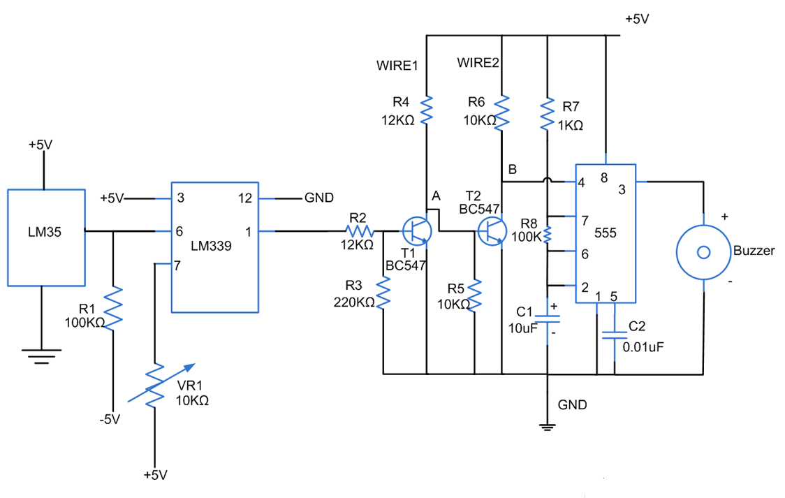
Fires can occur for several reasons, such as forgetting to turn off equipment like irons. A fire alarm circuit with a temperature sensor may be one option to secure homes from fire hazards. There are also fire alarm circuits...