
ISP microcontroller PLC implement method

The microcontroller serves as the core of the PLC, functioning similarly to hardware that monitors and controls the system. The microcontroller operates in a serial manner, while the PLC utilizes a cyclic scanning mode that includes three stages: input sampling, program execution, and output. These stages run concurrently, allowing for concentrated output handling.
In a typical operation, the PLC gathers the state of the input terminals in real-time and processes this data according to the ladder diagram programming. The results are stored in an output buffer, which is then sent to the corresponding output terminals. This process completes one scanning cycle, after which the next cycle begins automatically.
Although there is I/O hysteresis, the microcontroller executes commands in microseconds, while the scanning period may take several milliseconds, with a maximum of dozens of milliseconds. The scanning period can be viewed as a transient cycle for the input states, ensuring real-time control requirements are met.
The microcontroller features a RAM of 1k bytes and a FLASH memory of 64k bytes, eliminating the need for external memory expansion. The interface pins P0 to P3 serve as I/O ports. The input terminals connect to P0, which is isolated by opto-isolators for switch inputs. When a switch is closed, the corresponding pin reads '1', and when open, it reads '0'. During input sampling, the microcontroller reads the state of P0 and writes it to the input buffer.
P2 serves as the output latch for the PLC. During output operations, the content of the output buffer is unloaded to P2, which drives the output unit through isolated opto-isolators connected to its eight pins. P3 connects peripheral hardware such as keyboards, display units, and miniature printers, allowing the PLC to operate independently from a host computer. P1 functions as an I/O expansion interface; if the required I/O points exceed those provided by P0 and P2, additional I/O can be added through P1. Pins P1.6 and P1.7 can be used for software simulation tasks.
This design enables a robust and flexible PLC system suitable for a variety of industrial applications, supporting real-time processing and control through its efficient architecture and comprehensive I/O capabilities.It is obvious, a slice of SM2965 includes canonial 80C32, FLASH, E2PROM 28SF512, SRAM static data storage And WDT watchdog`s timer SM2965 is that the cost performance is extremely quite high The one piece Computer. And its ISP characteristic makes FLASH E2PROM can be regarded as the space of procedure, can also keep the data like E2PROM.Regard it as PLC that core design, have l
ow cost, be small, expand advantage convenient and flexible in usage. Regard microcontroller as the core and design PLC, it is basically the same that its hardware makes up and observes and controls the system as the microcontroller. But in the microcontroller observes and controls the system, examine And accuse of Course to be serial relation at time.
And PLC according to circulate scanning mode, carry on work, include, input sample, program execution and export, break 3 stages each period of scanning period, the relation operating mode runs side by side in inputting, concentrated output to adopt concentrating on. If like the microcontroller observes and controls the system, gather the state of the leading-in terminal to the line of procedure of PLC ladder-diagram in real time sequentially, the real-time output after process, can not reach the control result of PLC.
For this reason, set up, input, buffer as input the intersection of map and register in the intersection of RAM and district, adopt and at one time read in all leading-in terminal states, and store it in the input buffer, then, according to the logical relationship of the line of procedure of ladder-diagram, read the corresponding leading-in terminal state from the input buffer, operation stores the result to be outputted in the output buffer map register of the component after dealing with. Finally, finish all as the intersection of ladder-diagram and line of procedure, lump-sum to output the value of the output buffer to the corresponding lead-out terminal, through the above-mentioned three stages, finish a procedure scanning period.
Reciprocate so, carry on the scanning of the next one automatically. Work with walking abreast industrial control system two kinds of relations, coordinating serial program like this. Though the I/O hysteresis exists, the microcontroller`s time to carry out a order is microsecond grade, it is several milliseconds to carry out one and scan periodic time, maximum is dozens of milliseconds.
As to pick-up time of the electric apparatus, scanning period is transient, can be thought to sweep cycle inner state of the leading-in terminal in one to be invariable, collection and treatment of its change of state are real time, thus has met the requirement for real time control. This microcontroller has RAM of byte of FLASH memorizer and 1k of 64k byte, needn`t expand the external memory storage, its interface P0- P3 can all serve as I/O.
The leading-in terminal is connected to P0 8 oral feet after the photoelectricity is isolated. For the input of switch quantity. When the switch is put through, the corresponding pin is 1 , At the time of the switch off, the corresponding pin is 0 . During the course of inputting and sampling, MCU microcontroller Read P0 oral state, the write input buffer is to input the register of the map.
P2 mouth regarded as the output latch of PLC. During the course of exporting and breaking, the latch once to P2 of content unloading of the output buffer, actuating mechanism of the output unit of direct drive after the photoelectricity is isolated of 8 pins of P2 mouth. P3 mouth connects peripheral hardware such as the keyboard, display unit and miniature printer with PLC, makes PLC break away from the host computer and use singly.
P1 is regarded as I/O extended interface, when inputting, the point size of output unit required I/O exceeds I/O point size that P0 and P2 offer, can be expanded through I/O expanding element by P1 mouth. Use P1. 6 and P1. 7 a software simu 🔗 External reference
Related Circuits
The AVR 8-Bit RISC microcontroller from Atmel is a widely used microcontroller. This microcontroller integrates EEPROM, RAM, an Analog to Digital converter, numerous digital input and output lines, timers, UART for RS-232 communication, and various other features. An article...
SPI stands for Serial Peripheral Interface, which is the simplest among all communication protocols. Eight-bit data registers in the devices are connected by wires. These data registers function as shift registers, with one device controlling the data exchange within...
The initial PIC program utilizing the C language demonstrates how to blink a single LED using a PIC microcontroller with a C program. This serves as an introduction to C programming for PIC microcontrollers. The circuit for blinking an LED...
Using a switch to power up your microcontroller projects may not be a good idea if you need to "wake" the PIC during some events. For example: A metal detector sends a pulse indicating a car is ready to...
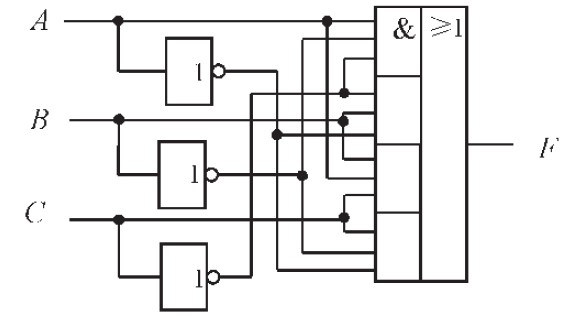
The design of the combinational logic circuit is diverse. An example chosen for detailed explanation is the implementation of an even parity check circuit. The parity check circuit exhibits particular characteristics and practicality in the analysis and design of...
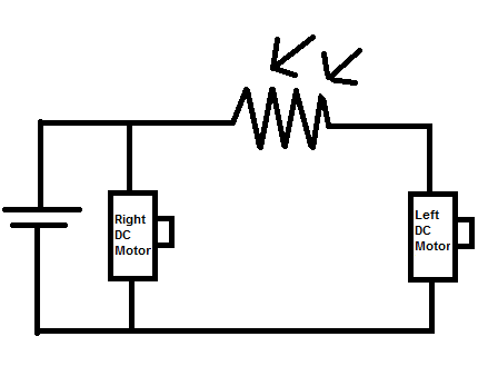
Construct a toy device that spins to the left whenever there is an obstruction in front of it, without utilizing a microcontroller. The proposed design involves using two DC motors as the rear wheels. An LDR (Light Dependent Resistor)...