
Simple Robot That Drives Forward and Back
Thus, this is a good robot project for beginners. Avid fans of Robot Room will recognize the 7474 chip from the Laser Control project. This chip has two independent one-bit memory cells. You can read all of the operational details and see a movie in that article. Briefly, the 7474 has a set (pin 10) and a clear (pin 13). The rear bumper switches are connected to the clear pin. When the rear bumper is pressed, the chip`s output (pin 9) is cleared (0V). This output connects to the motor driver chip and makes the robot drive forward. The function of the 7474 is to remember the output state even after the bumper is released. The front bumper switches are connected to the set pin. When the front bumper is pressed, the chip`s output (pin 9) is set (5V), rather than clear (0V). This commands the motor driver chip to drive the motor backwards. The 7474 remembers this new output. An oddity of the 7474 chip is that the set and clear pins are activated by a low (GND 0V) signal. Therefore, resistors R4 and R5 provide a high (5V) signal by default, so that the chip will not normally think that the set or clear pins are being activated. The bumper switches connect the appropriate pin to 0V when pressed, to activate the set or clear feature.
The power switch (SW1) connects the circuit to the battery when turned on. The diode (D1) prevents electricity from flowing in the wrong direction if the batteries are inserted backwards. Current is only allowed to flow in the direction of the arrow on the diode symbol. Backwards batteries would otherwise destroy the chips. Capacitors C2 and C3 provide a smooth, local power source as the battery voltage goes up and down with power consumption.
This helps prevent the chip from resetting or randomizing due to random electrical noise. Bonus: The laser project only needs the bottom half of the 7474 flip-flop chip, and this project only needs the top half. You can combine the circuits to make a robot that starts and stops with a laser pointer, and that goes forward and reverse based on bumpers.
You`ll need to substitute the motor driver on this page for the FAN8200 motor driver chip. Simply connect the laser output (pin 6) of the 7474 to the enable pin (2) on the FAN8200, and the direction output (pin 9) of the 7474 to the input pin (6) on the FAN8200. Snap-action switches have a nice feature where they can activate when the switch is pressed (normally-open pin) or when not pressed (normally-closed pin).
In this case, we only want the 7474 chip to receive 0V when a switch is pressed, so the 0V (GND) wire is soldered to normally-open and the signal wire is soldered to common. Notice that the front bumper switches are wired together (both connect to GND and both connect to the 7474 input pin 10).
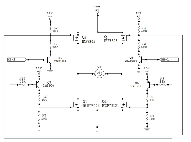
It doesn`t matter which switch is pressed - or even if both are pressed at the same time. In any case, the input pin gets connected to ground. The same goes for the rear bumper switches. The IXDN604 chip isn`t officially a motor driver chip. It`s actually a power MOSFET driver chip. However, it does an acceptable job supplying power to small motors. A similar setup is described on my H-bridge page. The IXDN604 is featured in Intermediate Robot Building. Both are good sources of information if you want more details. I usually place four diodes on the motor outputs, but that`s optional for a low-end project since MOSFETs have built-in body diodes. Admittedly, a MOSFET driver chip is a borderline poor choice for the 4. 5V-6V voltage level of this robot. MOSFETs perform better at higher voltages. This is not a criticism of the IXDN604 chip. The 🔗 External reference
Related Circuits
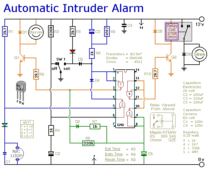
This is a simple single-zone burglar alarm circuit. Its features include automatic exit and entry delays and a timed bell/siren cut-off. It is designed to be used with the usual types of normally-closed input devices such as magnetic reed...
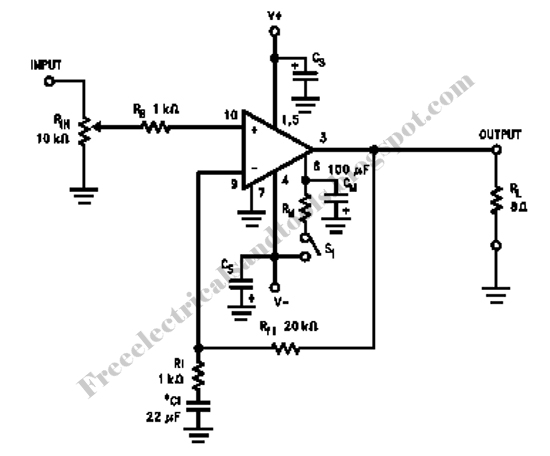
This is a design circuit for a simple function generator. Built around a single 8038 waveform generator IC, this circuit produces sine, square, or triangle waves from 20Hz to 200kHz in four switched ranges. There are both high and...
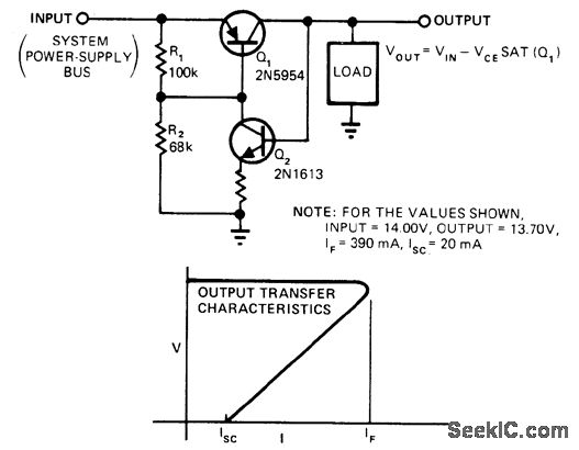
This circuit provides overload and short-circuit protection for a load while isolating malfunctioning circuits from other loads on a common supply bus. During normal operation, transistor Q1 is in saturation. When the load attempts to draw more current than...
The TINAH board shield is a printed circuit board designed for the Phys253 course, first utilized in 2009 by Engineering Physics students and faculty. This shield functions as a buffer to protect the digital and analog inputs and outputs...
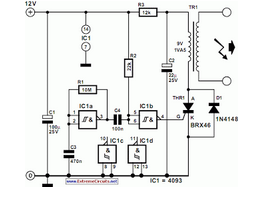
The circuit is designed for conducting safe experiments with high-voltage pulses and operates similarly to an electrified fence generator. This circuit is engineered to generate high-voltage pulses suitable for educational purposes and experimentation. The design is inspired by electrified fence...
Alternative display methods exist beyond the original 8 LED frequency counter, potentially offering improved readability and a more suitable format for QRP equipment. This document presents examples of binary decimal displays. Typically, the counter omits the MHz position, focusing...
Warning: include(partials/cookie-banner.php): Failed to open stream: Permission denied in /var/www/html/nextgr/view-circuit.php on line 713
Warning: include(): Failed opening 'partials/cookie-banner.php' for inclusion (include_path='.:/usr/share/php') in /var/www/html/nextgr/view-circuit.php on line 713