
Three-phase motor overcurrent protection circuit

The three-phase electric motor overcurrent protection circuit is designed to safeguard the motor against excessive current conditions that could lead to overheating and failure. The circuit employs a transformer for current sensing, which is crucial for real-time monitoring of the current flowing through each phase of the motor. The overcurrent relay (K1) is calibrated to a specific threshold; if the current exceeds this threshold, K1 activates, opening its normally closed contacts. This action interrupts the power supply to the contactor (KM), effectively disconnecting the motor from the power source and preventing potential damage.
To manage the high inrush current that occurs during motor startup, a time relay is integrated into the circuit. This relay temporarily shorts the current transformer, allowing the motor to start without triggering the overcurrent protection mechanism. This design consideration is essential, as the initial current can be significantly higher than the motor's normal operating current. Once the motor reaches its operational state and the current stabilizes, the time delay relay (KT) resets, enabling K1 to resume monitoring the current levels.
The circuit's design emphasizes reliability and responsiveness, ensuring that the motor is protected without hindering its performance during startup. By incorporating both the current sensing transformer and the time delay relay, the circuit effectively balances protection and operational efficiency, making it suitable for various industrial applications where three-phase motors are utilized. Proper implementation of this protection circuit can significantly extend the lifespan of electric motors and reduce maintenance costs associated with overcurrent-related failures.A three-phase electric motor is over- current protection circuit. How it works: This example circuit uses a transformer to sense the current, three-phase motor currents exceedi ng normal operating current time. Overcurrent relay Kl pull current reaches the set value of the suction, the normally closed contacts disconnect, KM loss of power release, the main circuit power loss t thereby protecting the electric motor, to disconnect when the over-current power supply. When the motor starting current is large, with a time relay normally closed contact to the current transformer shorting avoid motor starting current flows Kl and malfunction.
Motor starting to be completed after the current is reduced to normal, by the delay time relay KT move for the normally closed contacts disconnect, normally open contact closure, the KI access current transformer circuits.
Related Circuits
Crystal 80mW FM transmitter circuit diagram of the production The Crystal 80mW FM transmitter circuit is designed to generate frequency modulated (FM) signals suitable for short-range audio transmission. This circuit primarily consists of a crystal oscillator, which serves as...
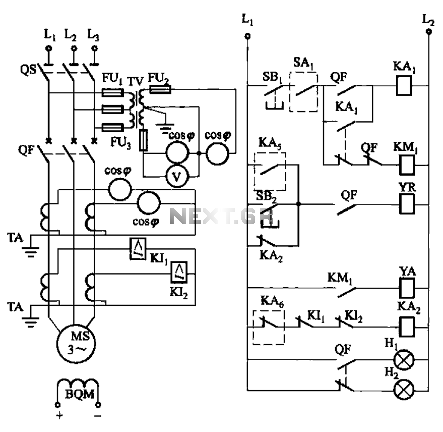
The circuit depicted in Figure 3-186 includes an isolation switch, QF vacuum circuit breakers, YR line for the circuit breaker coil, and YA for the circuit breaker closing coil. Additionally, there is a dashed box representing the excitation device...
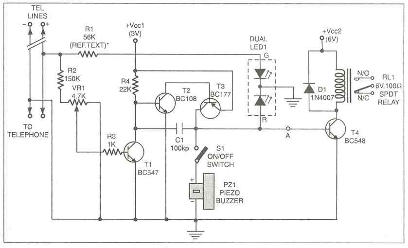
Multipurpose circuit for telephone. This add-on device for telephones can be connected in parallel to the telephone instrument. The circuit provides audio-visual indication of on-hook. This multipurpose circuit serves as an enhancement for standard telephone systems by providing both audio...
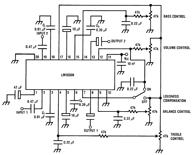
The LM1036 is a DC-controlled circuit designed for adjusting tone (bass and treble), volume, and balance in stereo applications such as car radios, televisions, and audio systems. It features an additional control input for straightforward loudness compensation. The circuit...
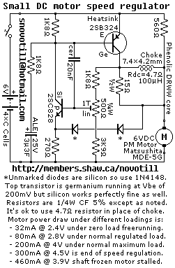
Reverse engineered circuit diagram of a motor speed regulator out of a portable pocket tape recorder containing a single motor for all functions. This circuit works amazingly well, keeping the motor speed constant regardless of shaft load and battery...

A simple transistor amplifier circuit diagram and schematic that can be used as a 12-watt audio transistor amplifier. An operational amplifier (op-amp) integrated circuit (IC) is used to produce the required gain. This circuit is designed to amplify audio signals,...