
Small DC Motor Speed Regulator
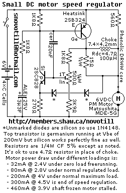
The circuit diagram of the motor speed regulator is designed to maintain a consistent motor speed in a portable tape recorder, irrespective of variations in load and supply voltage. The primary components of the circuit typically include an operational amplifier, a variable resistor (potentiometer), a transistor, and feedback mechanisms.
The operational amplifier is configured to monitor the voltage across the motor. It compares the actual speed of the motor, indicated by the voltage, with a reference voltage set by the potentiometer. This reference voltage can be adjusted to set the desired motor speed.
When the load on the motor changes, causing the speed to deviate from the set point, the operational amplifier outputs a control signal. This signal drives the transistor, which acts as a switch to adjust the power supplied to the motor. The transistor's duty cycle is modulated based on the feedback from the operational amplifier, ensuring that the motor receives the appropriate amount of power to maintain the desired speed.
Additionally, the circuit may include protective components such as diodes to prevent back EMF from the motor, which could potentially damage the circuit. Capacitors may also be present to filter noise and stabilize the voltage supply.
The overall design emphasizes efficiency and reliability, allowing the tape recorder to function optimally under various operational conditions. This motor speed regulator circuit exemplifies a robust solution for applications requiring precise speed control in small electronic devices.Reverse engineered circuit diagram of a motor speed regulator out of a portable pocket tape recorder containing a single motor for all functions. This circuit works amazingly well, keeping the motor speed constant regardless of shaft load and battery voltage.
🔗 External reference
Related Circuits
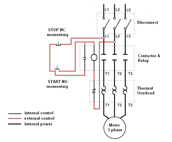
Wiring a three-phase motor through a two-pole vacuum switch involves two lines passing through the switch while one line remains continuously energized to the motor. Is this configuration correct, or does it present a safety concern? When wiring a three-phase...
The following circuit illustrates the circuit diagram of a motor control unit. This circuit is based on the LM317 integrated circuit (IC). Features include diodes that protect the regulator. The motor control unit circuit utilizes the LM317 voltage regulator to...
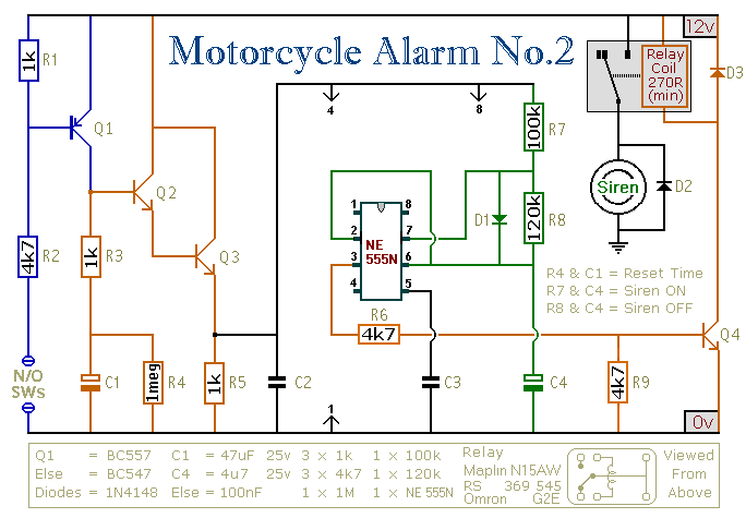
This circuit features an intermittent siren output and automatic reset. It can be operated manually using a key switch or a hidden switch, and it can also be wired to activate automatically when the ignition is turned off. By...

Low power 5V switching regulator power supply. Visit the corresponding page for an explanation of the related circuit diagram. The low power 5V switching regulator is designed to efficiently convert a higher input voltage to a stable 5V output while...
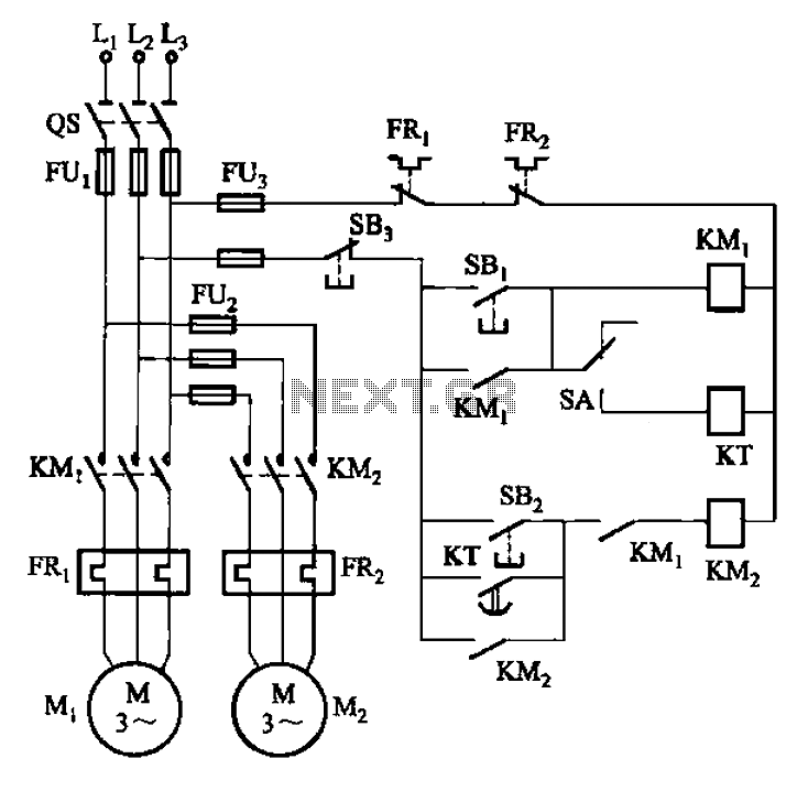
The circuit illustrated in Figure 3-85 features both manual and automatic control through the transfer switch SA. After initiating the motor Mi, an automatic start sequence is achieved via the time relay KT. The circuit employs a transfer switch (SA)...
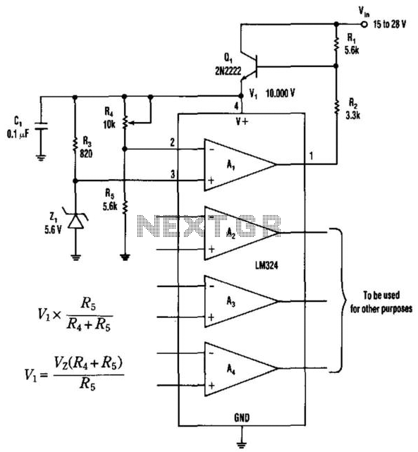
This operational amplifier provides a simple approach to creating a single-polarity stable voltage source. The transistor Q1 receives base drive through resistor R1 and conducts to generate a voltage (Vi) across the integrated circuit's supply pins. The operational amplifier...