
Three phase torque motor speed control circuit

The circuit design in Figure 3-176 focuses on achieving stable motor operation through effective voltage regulation. The use of a three-phase voltage regulator is critical for maintaining consistent voltage levels across the motor phases, which ensures that the motor runs smoothly and efficiently. This regulator compensates for fluctuations in input voltage and load conditions, allowing the motor to reach and maintain its equilibrium state.
The adjustment range of the circuit is a significant advantage, as it enables flexibility in operation. This feature is particularly beneficial in applications where varying load conditions are expected, as it allows for optimal performance across a broader spectrum of operational scenarios. However, the requirement for a three-phase voltage regulator implies an increase in complexity and cost. This component must be carefully selected and integrated into the circuit to ensure it can handle the power levels and operational demands of the motor.
In summary, the circuit in Figure 3-176 provides an effective solution for motor control with a wide adjustment range, though it does come with the trade-off of higher costs associated with the necessary three-phase voltage regulation. Proper design considerations must be taken into account to optimize performance while managing the associated costs. Circuit shown in Figure 3-176. This adjustment method, the motor can run at equilibrium, adjustment range and relatively wide. But requires a three-phase voltage regulator, hig her input costs.
Related Circuits
This project involves a light-activated alarm or morning alarm circuit that produces a pleasant melody upon detecting light. To use this circuit as a morning alarm, it should be placed in a location that receives morning sunlight. A 500K...
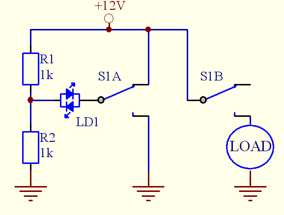
Assistance is needed for a project involving the construction of a switch panel. The individual has a good understanding of 12V electrical wiring but is encountering difficulties with this specific task. The project involves designing a switch panel that can...
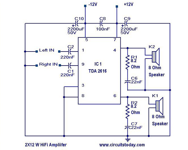
A simple Hi-Fi amplifier circuit diagram with a schematic for creating an audio amplifier, designed using the TDA 2616 integrated circuit (IC), which is a stereo power amplifier. It is suitable for use with radios, tape players, and televisions,...

A VU (Volume Unit) meter has traditionally been a key component of audio metering systems. The Peak Program Meter (PPM) is known for its inadequacy in accurately displaying peak signal levels. This circuit serves the same function as previously...
A battery-status indicator circuit is useful for monitoring portable test equipment and similar devices. LED D1 flashes to attract the user's attention, signaling that the circuit is operational, preventing it from being left on unintentionally. The circuit produces approximately...
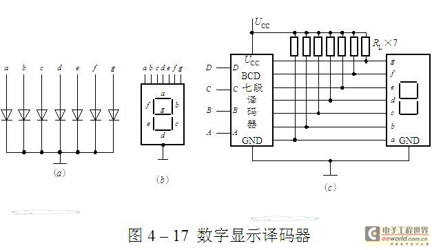
The luminescent diode (LED) is constructed from gallium arsenide (GaAs), a specialized semiconductor material, and gallium arsenide phosphide. It can be used individually or assembled into segment-type or lattice LED display devices. The display unit consists of a sectional...