
VU and PPM Meter Circuit for Audio

The VU meter circuit is designed to provide a reliable indication of audio signal levels, essential for sound engineers and audio professionals. The LM1458 dual op-amp serves as the heart of the circuit, providing amplification and rectification of the audio signal. The output from the op-amp is then fed into a rectifier stage, which converts the AC audio signal into a DC signal suitable for driving the VU meter.
The choice of rectification method is crucial for the performance of the VU meter. While some low-cost designs use a single diode, which can introduce inaccuracies, a selenium or germanium bridge rectifier offers better performance by minimizing signal loss and improving the meter's response to audio signals. The inclusion of a capacitor in the circuit smooths out the rectified signal, providing a more stable reading on the VU meter. However, in budget designs, the absence of this capacitor can lead to erratic meter behavior.
Ballistic response is a critical aspect of VU meter design. The circuit includes adjustable components (R6, C1, C2, and C3) to tailor the response time of the meter to match the specifications of the meter movement being used. Different meters have varying response characteristics, necessitating empirical testing to achieve optimal performance. The use of a 300 ms burst waveform allows for precise calibration, ensuring that the meter reaches near full scale with minimal overshoot, which is essential for accurate audio level representation.
In summary, the VU meter circuit combines amplification, rectification, and filtering to provide a visual representation of audio signal levels. Proper component selection and calibration are vital to achieving accurate and reliable readings, making this circuit an invaluable tool in audio metering systems.A VU (Volume Unit) meters used to be the mainstay of audio metering system. The Peak Program Meter (PPM) is notoriously bad at showing the peak signal level. This is a circuit that have function same of the explanation in above. In this circuit, the amplifier/rectifier is a simple LM1458 or similar dual op-amp, and buffers the rectifier circuit. T his is the figure of VU meter; The principle of the VU meter is a single diode is used in some, but the better ones will generally use a tiny selenium bridge rectifier or a germanium diode bridge. A capacitor is show, few budget VU meters will include it. As a result, the meter movement itself is uncontrolled in most of these meters, so overshoot is often huge, and the reading is almost useless.
Because of the diode forward voltage, many of these meters also fail completely to register low level signals (< -20 dB). In figure 2, is shown of the meters ballistic control for the VU meter. The principle of this circuit is the values of R6, C1, C2 and C3 may need to be adjusted, depending upon the ballistics of the meter movement you use.
Because meters vary so widely in this respect, it is only possible to provide representative values, although they should work quite well in practice. In order to get exact VU meter ballistics, it will be necessary to test the meter with a 300ms burst waveform at full scale (+3VU).
It should reach 99% of full scale with up to 1% of overshoot before dropping back to zero. If we want to know about the result of the VU meter testing, we must make the circuit. 🔗 External reference
Related Circuits
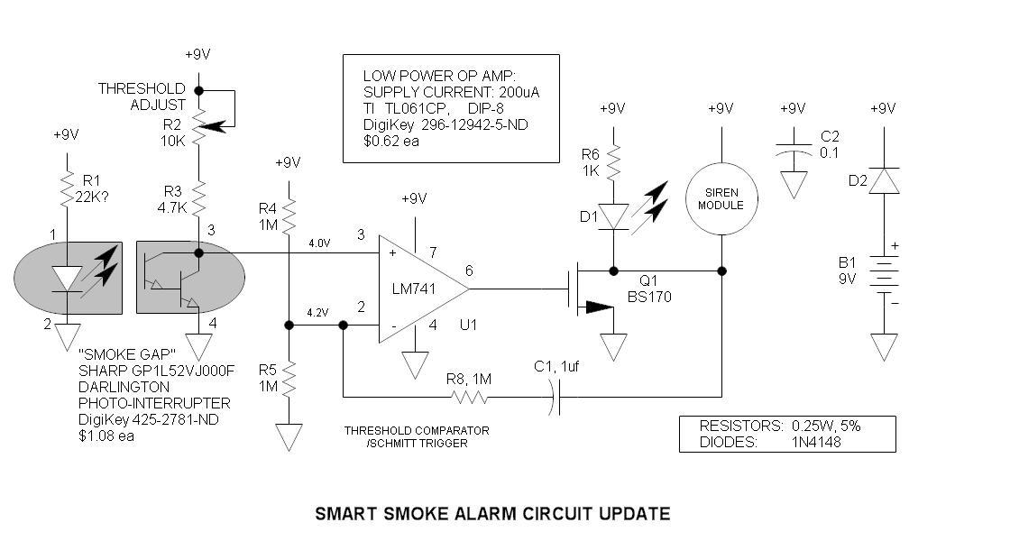
The original smoke alarm circuit has several issues that have left hobbyists and students dissatisfied. Instead of trying to resolve its numerous problems, an updated version has been created using the well-known LM741 op-amp. This new design is simpler,...
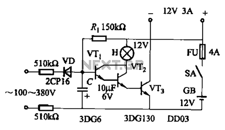
An AC-DC power supply without a power switching circuit is typically utilized for lighting load circuits. Once the power grid is restored, the standby power supply automatically switches on. An automatic switching circuit using a transistor is implemented, with...
Observe the left side of the circuit, which includes a sensing coil and an operational amplifier (op-amp). When connected as shown in the schematic, the circuit did not pick up any signals. A 1mH radial inductor was not available,...
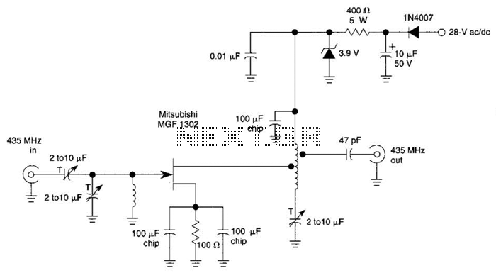
This circuit is a low-noise preamplifier designed for the 435-MHz amateur satellite frequencies. It utilizes a Mitsubishi MGF1302 transistor. A 28-Vdc power source is indicated; however, lower voltages can be employed by adjusting the 400-5-W resistor. The low-noise preamplifier circuit...
The circuit schematic is straightforward. Information regarding the assembly and testing of circuits is not provided, as there are many instructional resources available. The circuit schematic in question is designed to be simple and user-friendly, allowing for ease of understanding...

The Pyro Propeller Clock POV schematic is relatively straightforward. It consists of three primary components: the power supply utilizing a 7805 voltage regulator, the LED output control managed by a PIC18F252 microcontroller and a 74LS373 latch, and the 'home'...